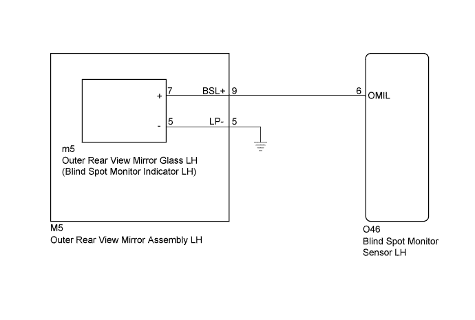
DTC C1AB3 Short to GND in Outer Mirror Indicator(Slave) |
| DTC Code | DTC Detection Condition | Trouble Area |
| C1AB3 | With the blind spot monitor main switch assembly (warning canceling switch assembly) on, the voltage output from the blind spot monitor sensor to the indicator is low for a certain amount of time. |
|
| 1.CHECK DTC |
Clear the DTCs (Click here).
Recheck for DTCs and check if the same DTC is output again.
|
| ||||
| OK | ||
 | ||
| ||
| 2.CHECK HARNESS AND CONNECTOR |
Disconnect the O46 blind spot monitor sensor LH connector.
Disconnect the M5 outer rear view mirror assembly LH connector.
Measure the resistance according to the value(s) in the table below.
| Tester Connection | Condition | Specified Condition |
| M5-9 (BSL+) - Body ground | Always | 10 kΩ or higher |
|
| ||||
| OK | |
 |
| 3.INSPECT OUTER REAR VIEW MIRROR GLASS LH (OUTER REAR VIEW MIRROR INDICATOR LH) |
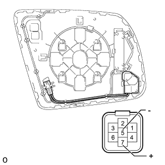 |
Remove the outer rear view mirror glass LH (Click here).
Check the outer rear view mirror indicator.
Apply battery voltage to the outer rear view mirror glass LH (outer rear view mirror indicator LH) and check that the outer rear view mirror indicator turns on.
| Connection | Specified Condition |
| Battery positive (+) → Terminal 7 (+) Battery negative (-) → Terminal 5 (-) | Indicator turns on |
|
| ||||
| OK | |
|
| 4.CHECK HARNESS AND CONNECTOR |
Disconnect the m5 outer rear view mirror glass LH connector.
Measure the resistance according to the value(s) in the table below.
| Tester Connection | Condition | Specified Condition |
| O46-6 (OMIL) - Body ground | Always | 10 kΩ or higher |
|
| ||||
| OK | ||
| ||
| ||

