BODY WELD POINT FIT STANDARD / ADJUSTMENT METHOD ADJUSTMENT
INSPECT HOOD
Check that the clearance measurements are within the standard ranges.
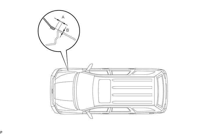
- Standard:
Area Measurement Area Measurement A 4.0 to 7.0 mm
(0.157 to 0.276 in.)B -1.5 to 1.5 mm
(-0.059 to 0.059 in.)
- HINT:
-
Centering bolts are used to mount the hood hinge and hood lock. The hood and hood lock cannot be adjusted with the centering bolts in. Substitute standard bolts (with washers) for the centering bolts when making adjustments.
ADJUST HOOD
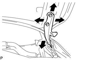
Loosen the 4 hood side hinge bolts.
Move the hood to adjust the clearance to within the standard range.
Tighten the 4 hood side hinge bolts after the adjustment.
- Torque:
- 13 N*m (133 kgf*cm, 10 ft.*lbf)
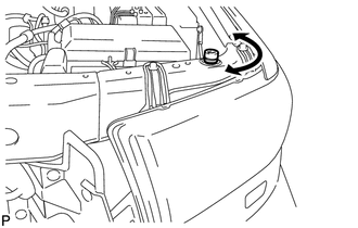
Adjust the height of the hood front end by turning the cushion rubber.
- HINT:
-
The cushion rubber can be raised and lowered by turning it.
Adjust the hood lock.
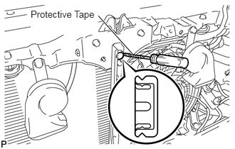
Remove the hood lock nut cap.
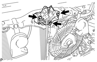
Loosen the 2 bolts and nut.
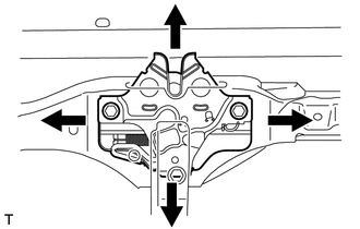
Adjust the hood lock position so that the striker can enter it smoothly.
Tighten the 2 bolts and nut after the adjustment.
- Torque:
- 8.0 N*m (82 kgf*cm, 71 in.*lbf)
INSPECT FRONT DOOR
Check that the clearance measurements are within the standard ranges.
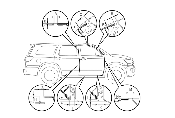
- Standard:
Area Measurement Area Measurement A 4.0 to 7.0 mm
(0.157 to 0.276 in.)H -1.5 to 1.5 mm
(-0.059 to 0.059 in.)B -1.5 to 1.5 mm
(-0.059 to 0.059 in.)I 7.8 to 10.8 mm
(0.307 to 0.425 in.)C 4.0 to 7.0 mm
(0.157 to 0.276 in.)J 1.9 to 4.9 mm
(0.075 to 0.193 in.)D 0.8 to 3.8 mm
(0.031 to 0.150 in.)K 7.8 to 10.8 mm
(0.307 to 0.425 in.)E 4.0 to 7.0 mm
(0.157 to 0.276 in.)L 2.3 to 5.3 mm
(0.091 to 0.209 in.)F 0.9 to 3.9 mm
(0.035 to 0.154 in.)M 4.0 to 7.0 mm
(0.157 to 0.276 in.)G 5.0 to 8.0 mm
(0.197 to 0.315 in.)N -1.5 to 1.5 mm
(-0.059 to 0.059 in.)
- HINT:
- ·
Use the same procedure for the RH and LH sides.
·The procedure described below is for the RH side.
·Centering bolts are used to mount the door hinge onto the vehicle body and door. The door cannot be adjusted with the centering bolts in. Substitute standard bolts (with washers) for the centering bolts when making adjustments.
ADJUST FRONT DOOR
Disconnect the cable from the negative battery terminal.
- CAUTION:
-
Wait at least 90 seconds after disconnecting the cable from the negative (-) battery terminal to disable the SRS system.
- NOTICE:
-
When disconnecting the cable some systems need to be initialized after the cable is reconnected.
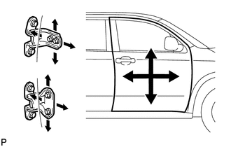
Using SST, adjust the door horizontally and vertically by loosening the body side hinge bolts.
- SST
- 09812-00010
Tighten the body side hinge bolts after the adjustment.
- Torque:
- 26 N*m (265 kgf*cm, 19 ft.*lbf)
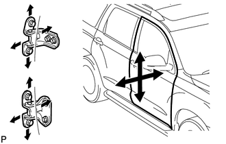
Using SST, adjust the door horizontally and vertically by loosening the door side hinge bolts.
- SST
- 09812-00010
Tighten the door side hinge bolts after the adjustment.
- Torque:
- 26 N*m (265 kgf*cm, 19 ft.*lbf)
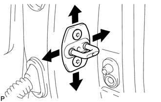
Using "TORX" socket wrench T40, adjust the striker position by slightly loosening the striker mounting screws and hitting the striker with a plastic-faced hammer.
Using "TORX" socket wrench T40, tighten the striker mounting screws after the adjustment.
- Torque:
- 23 N*m (235 kgf*cm, 17 ft.*lbf)
Connect the cable to the negative battery terminal.
- Torque:
- 5.4 N*m (55 kgf*cm, 48 in.*lbf)
- CAUTION:
-
When disconnecting the cable some systems need to be initialized after the cable is reconnected.
Inspect the SRS warning light.
INSPECT REAR DOOR
Check that the clearance measurements are within the standard ranges.
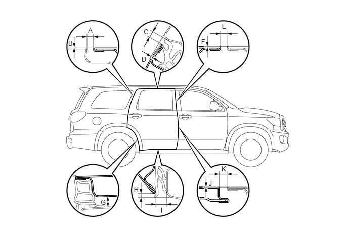
- Standard:
Area Measurement Area Measurement A 4.0 to 7.0 mm
(0.157 to 0.276 in.)G 8.0 to 12.0 mm
(0.315 to 0.472 in.)B -1.5 to 1.5 mm
(-0.059 to 0.059 in.)H 1.6 to 4.6 mm
(0.063 to 0.181 in.)C 4.0 to 7.0 mm
(0.157 to 0.276 in.)I 7.8 to 10.8 mm
(0.307 to 0.425 in.)D 0.6 to 3.6 mm
(0.024 to 0.142 in.)J -1.5 to 1.5 mm
(-0.059 to 0.059 in.)E 4.0 to 7.0 mm
(0.157 to 0.276 in.)K 5.0 to 8.0 mm
(0.197 to 0.315 in.)F -1.5 to 1.5 mm
(-0.059 to 0.059 in.)- -
- HINT:
- ·
Use the same procedure for the RH and LH sides.
·The procedure listed below is for the LH side.
·Centering bolts are used to mount the door hinge to the vehicle body and door. The door cannot be adjusted with the centering bolts on. Substitute the centering bolts for standard bolts when making adjustments.
ADJUST REAR DOOR
Disconnect the cable from the negative battery terminal.
- CAUTION:
-
Wait at least 90 seconds after disconnecting the cable from the negative (-) battery terminal to disable the SRS system.
- NOTICE:
-
When disconnecting the cable some systems need to be initialized after the cable is reconnected.
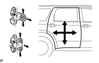
Using SST, adjust the door horizontally and vertically by loosening the body side hinge bolts.
- SST
- 09812-00010
Tighten the body side hinge bolts after the adjustment.
- Torque:
- 26 N*m (265 kgf*cm, 19 ft.*lbf)
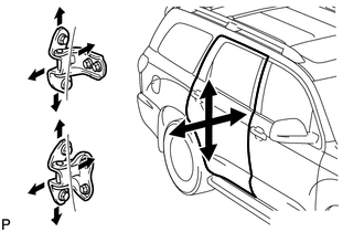
Using SST, adjust the door horizontally and vertically by loosening the door side hinge bolts.
Tighten the door side hinge bolts after the adjustment.
- Torque:
- 26 N*m (265 kgf*cm, 19 ft.*lbf)
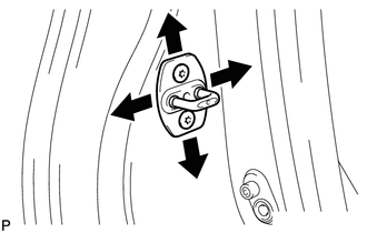
Using "TORX" socket wrench T40, adjust the striker position by slightly loosening the striker mounting screws and hitting the striker with a plastic-faced hammer.
Using "TORX" socket wrench T40, tighten the striker mounting screws after the adjustment.
- Torque:
- 23 N*m (235 kgf*cm, 17 ft.*lbf)
Connect the cable to the negative battery terminal.
- Torque:
- 5.4 N*m (55 kgf*cm, 48 in.*lbf)
- CAUTION:
-
When disconnecting the cable some systems need to be initialized after the cable is reconnected.
Inspect the SRS warning light.
INSPECT BACK DOOR
Check that the clearance measurements are within the standard ranges.
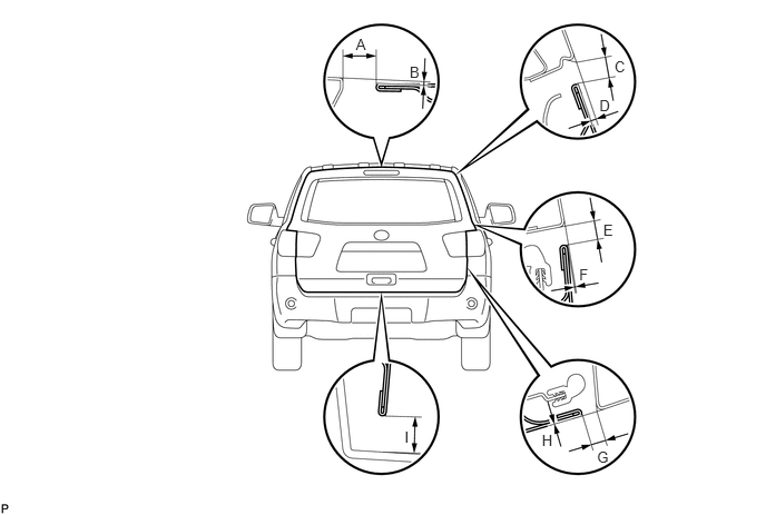
- Standard:
Area Measurement Area Measurement A 11.9 mm
(0.469 in.)F 0.2 mm
(0.008 in.)B 1.6 mm
(0.063 in.)G 6.0 mm
(0.236 in.)C 8.0 mm
(0.315 in.)H 0 mm
(0 in.)D 2.1 mm
(0.083 in.)I 15.1 mm
(0.594 in.)E 6.6 mm
(0.260 in.)- -
- HINT:
-
Centering bolts are used to mount the door hinge onto the vehicle body and door. The door cannot be adjusted with the centering bolts in. Substitute standard bolts (with washers) for the centering bolts when making adjustments.
ADJUST BACK DOOR
Disconnect the cable from the negative battery terminal.
- CAUTION:
-
Some of these service operations affect the SRS airbag system. Read the precautionary notices concerning the SRS airbag system before servicing.
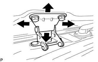
Adjust the door position.
Horizontally and vertically adjust the door by loosening the door side hinge bolts.
- Torque:
- 20 N*m (199 kgf*cm, 14 ft.*lbf)
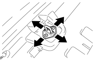
Adjust the striker position.
Using "TORX" socket wrench T40, adjust the striker position by slightly loosening the striker mounting screws and hitting the striker with a plastic-faced hammer.
Using "TORX" socket wrench T40, tighten the striker mounting screws after the adjustment.
- Torque:
- 27 N*m (275 kgf*cm, 20 ft.*lbf)
Connect the cable to the negative battery terminal.
- Torque:
- 5.4 N*m (55 kgf*cm, 48 in.*lbf)
- CAUTION:
-
When disconnecting the cable some systems need to be initialized after the cable is reconnectedZ.
Inspect the SRS warning light.