BODY ELECTRICAL MULTIPLEX COMMUNICATION GENERAL/CONTROL/DETAILS DESCRIPTION
DESCRIPTION
The multiplex communication system uses the 3 communication protocols (CAN, LIN, and AVC-LAN) to achieve a streamlined wiring harness configuration.
CAN (Controller Area Network) is classified into two types according to communication speed. The HS-CAN (High Speed CAN) is used for the power train, chassis and body electrical systems, and the MS-CAN (Medium Speed CAN) is used for the body electrical system.
LIN (Local Interconnect Network) is used for local area networking, of which the system has a respective bus for each body electrical system.
AVC-LAN (Audio Visual Communication - Local Area Network) is used for communication only between the AV (Audio Visual) system components.
HS-CAN consists of a V1 bus and a braking and driving bus, and MS-CAN consists of an MS bus. The main body ECU with gateway function is used to transmit data between the buses.
Due to the introduction of the CAN communication system for the power train, chassis and body electrical systems, the BEAN (Body Electronics Area Network) that is used for the body electrical system on other vehicles is not used on this model.
A customized body electronics system is used, enabling some of the control functions of the ECUs comprising the CAN to be set using a Techstream.
REFERENCE
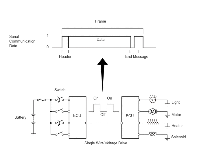
Multiplex communication refers to the use of serial communication data that consists of bits and frames in order to exchange information among various ECUs. This allows for a reduction of the amount of wiring on the vehicle.
A bit is the basic unit of communication that is used to represent the information. A bit is represented by binary values of "0" or "1".
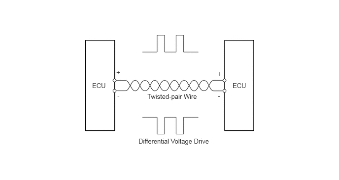
For CAN communication, a differential voltage drive is used to represent the binary values of "0" or "1". This "differential voltage drive" reduces the effects of electrical interference.