BODY ELECTRICAL MULTIPLEX COMMUNICATION GENERAL/CONTROL/DETAILS CAN
GENERAL
The CAN (Controller Area Network) uses two different CAN buses: V1 bus and braking and driving bus for high-speed communication (500 kbps) and MS bus for medium-speed communication (250 kbps).
The CAN has terminating resistors of 120 Ω which are necessary for accurate judgment of communication on the main bus.
The terminating resistors for the V1 bus are located in the ECM and the combination meter.
The terminating resistors for the MS bus are located in the main body ECU and the combination meter.
The combination meter is connected to MS bus only for the terminating resistor. The combination meter does not communicate using the MS bus.
The main body ECU has a gateway function and is used to transmit data between the V1 bus and the MS bus.
WIRING DIAGRAM
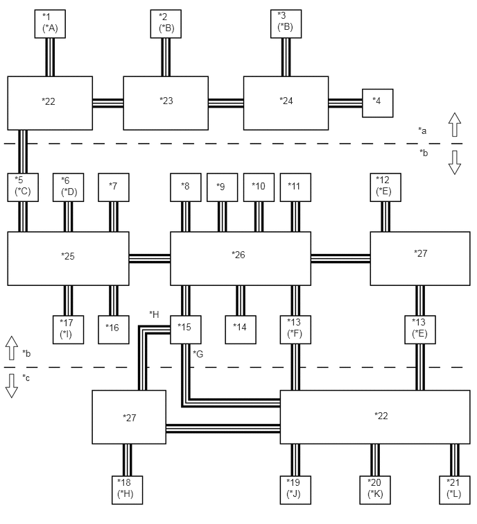
| *A | Models with Dynamic Laser Cruise Control System | *B | Models with Blind Spot Monitor System |
| *C | Models with Network Gateway ECU | *D | Optional Equipment |
| *E | Models with Rear Air Suspension System | *F | Models without Rear Air Suspension System |
| *G | Models without Power Back Door System | *H | Models with Power Back Door System |
| *I | 4WD Models | *J | Models with Power Seat System |
| *K | Models with Memory System | *L | Models with Power Tilt and Telescopic Steering Column |
| *1 | Distance Control ECU | *2 | Blind Spot Monitor Sensor LH |
| *3 | Blind Spot Monitor Sensor RH | *4 | No. 7 Junction Connector |
| *5 | Network Gateway ECU | *6 | Bus Buffer ECU |
| *7 | ECM | *8 | DLC3 |
| *9 | Steering Angle Sensor | *10 | Center Airbag Sensor Assembly |
| *11 | Skid Control ECU | *12 | Suspension Control ECU |
| *13 | Combination Meter | *14 | Power Steering ECU |
| *15 | Main Body ECU (Driver Side Junction Block) | *16 | Air Conditioning Amplifier Assembly |
| *17 | 4WD Control ECU | *18 | Power Back Door ECU |
| *19 | Driver Seat ECU | *20 | Mirror ECU |
| *21 | Tilt and Telescopic ECU | *22 | No. 3 Junction Connector |
| *23 | No. 5 Junction Connector | *24 | No. 6 Junction Connector |
| *25 | No. 2 Junction Connector | *26 | No. 1 Junction Connector |
| *27 | No. 4 Junction Connector | - | - |
| *a | V2 Bus | *b | V1 Bus |
| *c | MS Bus | - | - |
LAYOUT OF MAIN COMPONENTS
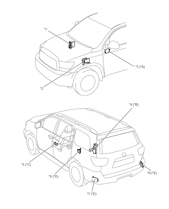
| *A | Models with Memory System | *B | Models with Power Back Door System |
| *C | Models with Power Seat System | *D | Models with Rear Air Suspension System |
| *E | Models with Blind Spot Monitor System | - | - |
| *1 | ECM | *2 | Skid Control ECU |
| *3 | Mirror ECU | *4 | Power Back Door ECU |
| *5 | Driver Seat ECU | *6 | Suspension Control ECU |
| *7 | Blind Spot Monitor Sensor LH | *8 | Blind Spot Monitor Sensor RH |
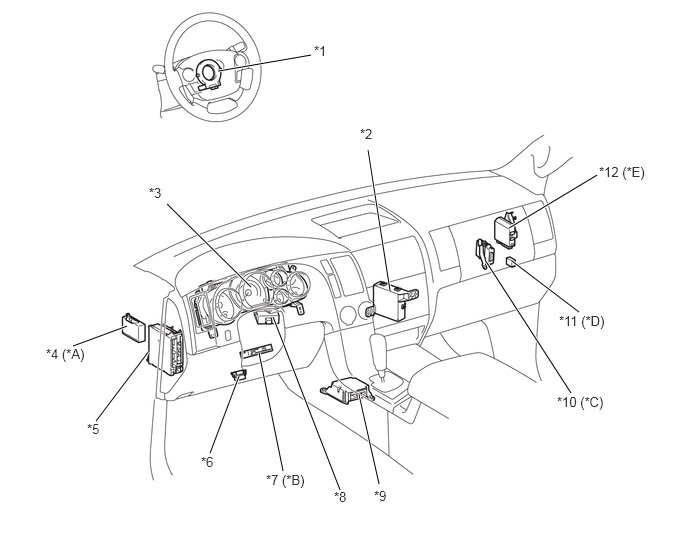
| *A | Models with Dynamic Laser Cruise Control System | *B | Models with Power Tilt and Telescopic Steering Column |
| *C | Models with Network Gateway ECU | *D | Optional Equipment |
| *E | 4WD Models | - | - |
| *1 | Steering Angle Sensor | *2 | Air Conditioning Amplifier Assembly |
| *3 | Combination Meter Assembly | *4 | Distance Control ECU |
| *5 | Main Body ECU (Driver Side Junction Block) | *6 | DLC3 |
| *7 | Tilt and Telescopic ECU | *8 | Power Steering ECU |
| *9 | Center Airbag Sensor Assembly | *10 | Network Gateway ECU |
| *11 | Bus Buffer ECU | *12 | 4WD Control ECU |