CHASSIS SUSPENSION AND AXLE GENERAL/CONTROL/DETAILS REAR AIR SUSPENSION SYSTEM AND ADAPTIVE VARIABLE SUSPENSION SYSTEM (AVS)
General
The rear air suspension system is standard equipment for the Platinum grade. Furthermore, the AVS system is standard equipment for the Platinum grade.
The rear air suspension system is a vehicle height control system that uses pneumatic cylinders in the rear suspension, instead of coil springs. This enables the vehicle to maintain a constant vehicle height regardless of the number of occupants or load, thus realizing excellent driving stability and ride comfort.
The AVS system controls the damping force of the shock absorbers for the four wheels in accordance with the driving conditions and road surface conditions. Thus, it realizes a comfortable ride, excellent drivability and stability at high levels.
Although the rear air suspension system and AVS system are controlled by the suspension control ECU, these systems are independent from each other.
| Rear Air Suspension | ·
This system uses pneumatic cylinders in stead of the coil springs. The suspension control ECU analyzes the information based on the switches, sensors, and input signals, operates the compressor and motor with dryer, and uses the solenoid valves to control the vehicle height. ·
The suspension control ECU detects, via the 2 height control sensors, the changes in the rear vehicle height that results from the number of occupants or the amount of the load. Then, the suspension control ECU controls the solenoid valves and the compressor and motor with dryer in order to automatically adjust the rear vehicle height to a constant (Normal) vehicle height. ·
Furthermore, three vehicle heights can be selected by operating the height control switch: HI, Normal, and LO. The HI vehicle height ensures the vehicle's driving performance on rough roads. The LO vehicle height facilitates the entry and exit of the occupants and the loading and unloading of cargo. The Normal vehicle height helps realize excellent controllability and riding comfort during normal driving. |
| AVS | ·
Through electronic control, AVS automatically controls the damping force of the shock absorbers, thus realizing excellent riding comfort and controllability. ·
The AVS is a semi-active type of suspension. Its suspension control ECU estimates the vehicle conditions based on the signals from the sensors and the absorber control switch. Then, the suspension control ECU actuates the actuators of the shock absorbers, vary the flow of the oil, and control the damping force. ·
Non-linear H∞ control is used for the basic control of the damping force. ·
By operating the absorber control switch, the driver can select 3 types of damping forces of the shock absorbers. |
- HINT:
-
To summarize, H∞ control is a theory for designing a controller that meets the control specifications that are represented by the H∞ norm (a unit of measurement of the transfer function of the system). When this is expanded into a non-linear system, it is called "non-linear H∞ control".
-
The "H" is the initial letter of the mathematician named Hardy (who studied the stability of control systems) who advocated the mathematical space that is handled by this control logic. The "∞" represents the ∞ norm, which is one of the mathematical units used for measuring the size of the signals.
- HINT:
-
Before raising the vehicle on a jack or hoist, make sure to press the height control mode select switch (manual mode) to prohibit height control.
System Diagram
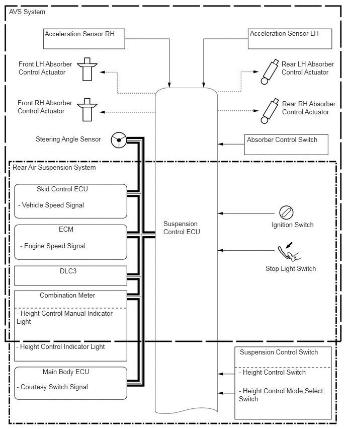
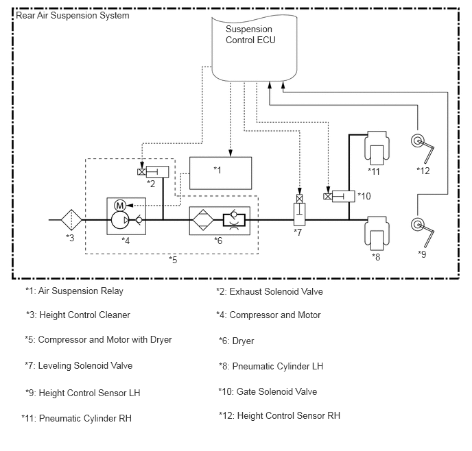
Wiring Diagram
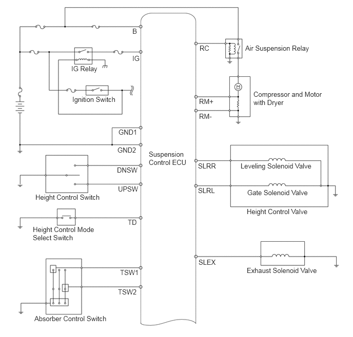
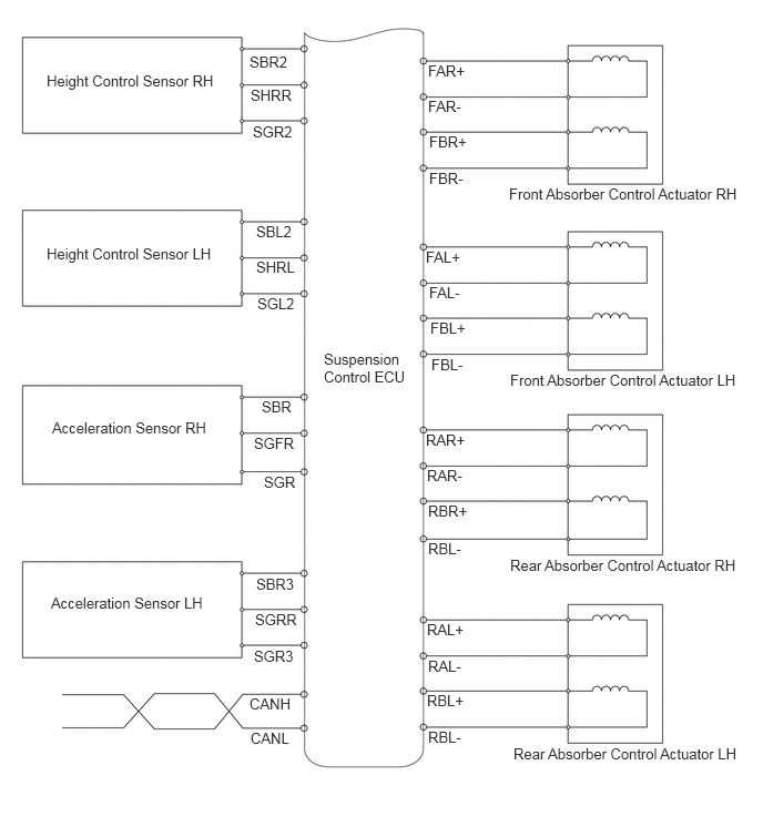
Layout of Main Components
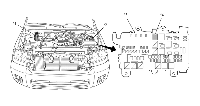
| *1 | ECM | *2 | Skid Control ECU |
| *3 | E/G Relay Block | *4 | Air Suspension Relay |
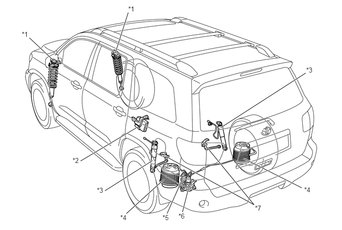
| *1 | Absorber Control Actuator | *2 | Suspension Control ECU |
| *3 | Rear Shock Absorber
·
Absorber Control Actuator |
*4 | Pneumatic Cylinder |
| *5 | Height Control Valve
·
Leveling Solenoid Valve ·
Gate Solenoid Valve |
*6 | Compressor and Motor with Dryer
·
Exhaust Solenoid Valve |
| *7 | Height Control Sensor | - | - |
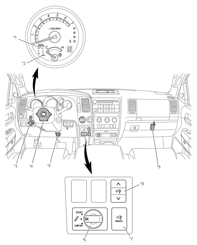
| *1 | Height Control Indicator Light | *2 | Height Control Manual Indicator Light |
| *3 | Acceleration Sensor LH | *4 | Steering Angle Sensor |
| *5 | DLC3 | *6 | Absorber Control Switch |
| *7 | Height Control Mode Select Switch | *8 | Height Control Switch |
| *9 | Acceleration Sensor RH | - | - |
Rear Air Suspension System Tubing Diagram
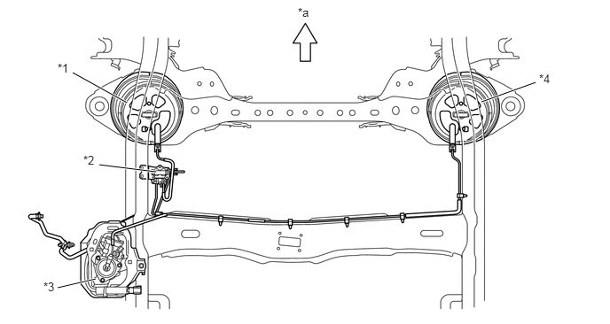
| *1 | Pneumatic Cylinder LH | *2 | Height Control Valve |
| *3 | Compressor and Motor with Dryer | *4 | Pneumatic Cylinder RH |
| *a | Front | - | - |
Function of Main Components
| Component | Function | |
|---|---|---|
| Compressor and Motor with Dryer | ·
Creates compressed air that is required for raising the vehicle height and supplies it to the pneumatic cylinder. ·
Removes moisture in the compressed air. |
|
| Exhaust Solenoid Valve | Discharges compressed air to the atmosphere from pneumatic cylinder to lower the vehicle height. | |
| Height Control Cleaner | Removes dust and sand from the internal air. | |
| Pneumatic Cylinder | Supports the vehicle body and adjusts the vehicle height. | |
| Height Control Valve | Leveling Solenoid Valve | Opens/closes the compressed air path between the compressor and motor with dryer and the pneumatic cylinder. |
| Gate Solenoid Valve | Opens/closes the compressed air path between the right and left pneumatic cylinders. | |
| Absorber Control Actuator | Changes the damping force of the shock absorbers. | |
| Height Control Sensor | Detects the vehicle height. | |
| Acceleration Sensor | Detects the vertical acceleration rate of the body. | |
| Speed Sensor | Detects the speed of the wheels. | |
| Steering Angle Sensor | Detects the steering direction and angle of the steering wheel. | |
| Height Control Mode Select Switch | ·
Sets the vehicle height control to the manual mode and prohibits automatic height control. ·
Sets the vehicle height control to the auto mode. |
|
| Height Control Switch | ·
Selects vehicle height (HI, Normal, or LO). ·
Sets the vehicle height to a desired position (when the manual mode is selected). |
|
| Absorber Control Switch | Switches the damping force control modes. | |
| Door Courtesy Switch | Detects the open/close condition of the doors. | |
| Back Door Courtesy Switch | Detects the open/close condition of the back door. | |
| Stop Light Switch | Detects the brake pedal depressing signal. | |
| Combination Meter | Contains an indicator, and displays the selected conditions of the height control mode select switch and height control switch (and absorber control switch). | |
| Suspension Control ECU | Estimates the condition of the vehicle in accordance with the signals provided by the sensors and switches, and outputs control signals to the compressor and valves (and absorber control actuators). | |
| ECM | Receives the signal of the crankshaft position sensor and sends it to the suspension control ECU. | |
Construction and Operation of Main Components
Compressor and Motor with Dryer
The compressor and motor are used to make the compressed air necessary for raising the vehicle height.
The exhaust solenoid valve is provided on the compressor and motor. The exhaust solenoid valve discharges compressed air from the pneumatic cylinders to the atmosphere in order to lower the vehicle height.
The dryer is used to eliminate the moisture in the compressed air made by the compressor and motor.
To protect the battery, this compressor and motor with dryer operates only when the engine is running.
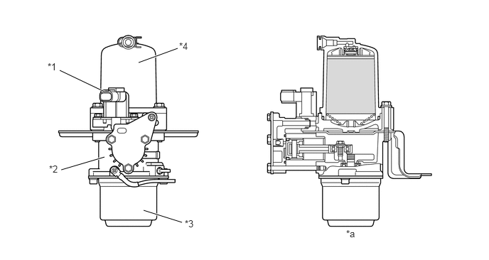
| *1 | Exhaust Solenoid Valve | *2 | Compressor Portion |
| *3 | Compressor Motor | *4 | Dryer |
| *a | Cross Section | - | - |
Height Control Cleaner
The height control cleaner consists of a filter to remove dust and debris, and an expansion chamber to reduce the intake sound. In consideration of dusty areas, this cleaner draws air from the inside of the vehicle cabin.
This cleaner cannot be disassembled; therefore, it is not possible to replace only the filter element.
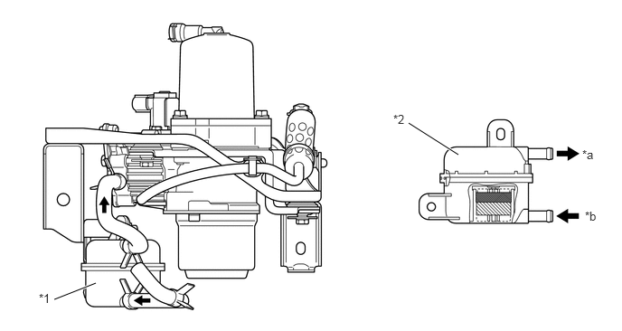
| *1 | Height Control Cleaner | *2 | Expansion Chamber |
| *a | OUT | *b | IN |
Pneumatic Cylinder
The pneumatic cylinder consists of a single type air chamber with a large compressed air capacity in order to realize excellent riding comfort.
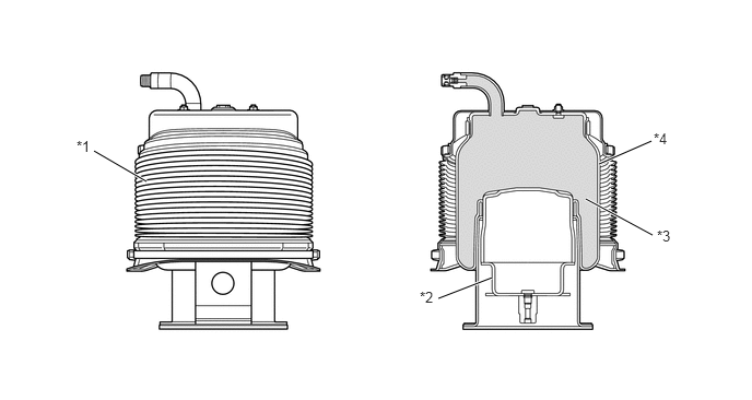
| *1 | Dust Cover | *2 | Piston |
| *3 | Chamber | *4 | Diaphragm |
- HINT:
-
To remove a pneumatic cylinder, perform the operation by supporting the frame, raising the rear axle on a jack, and leaving the shock absorbers attached in place.
-
For details, see the Repair Manual.
Height Control Valve
The height control valve consists of a leveling solenoid valve and a gate solenoid valve.

| *1 | Leveling Solenoid Valve | *2 | Gate Solenoid Valve |
Shock Absorber and Absorber Control Actuator
The front shock absorber is equipped with an external actuator. The piston rod is equipped with a rotary valve, a soft damping force valve and a hard damping force valve.
The piston rod of the rear shock absorber is equipped with an internal actuator. The piston rod is equipped with a rotary valve, a soft damping force valve and a hard damping force valve.
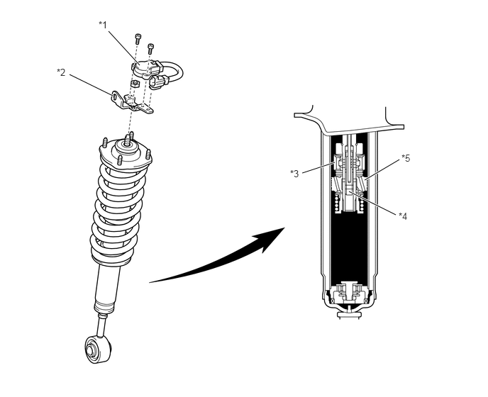
| *1 | Absorber Control Actuator | *2 | Actuator Bracket |
| *3 | Soft Damping Force Valve | *4 | Rotary Valve |
| *5 | Hard Damping Force Valve | - | - |
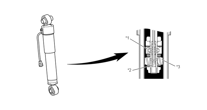
| *1 | Soft Damping Force Valve | *2 | Rotary Valve |
| *3 | Hard Damping Force Valve | - | - |
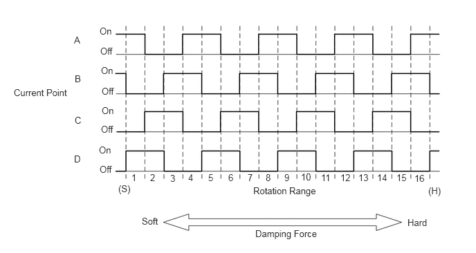
An absorber control actuator changes the damping force in accordance with the signals received from the suspension control ECU.
A 16-step step motor turns the rotary valve in the shock absorber to vary the opening of the oil passage. This enables the damping force to be changed smoothly.
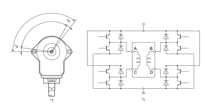
| *1 | Front Absorber Control Actuator | - | - |
| *a | Hard | *b | Soft |
| *c | Actuator Circuit | - | - |
Height Control Sensor
The height control sensor detects the vehicle height.
Along with the use of the independent suspension system, height control sensors have been provided on the left and right upper arms of the rear suspension.
The sensor has an arm that moves along with the change in vehicle height, and the resultant change in voltage enables the suspension control ECU to detect the vehicle height.
A semiconductor type of sensor is used to make it compact and temperature-resistant.
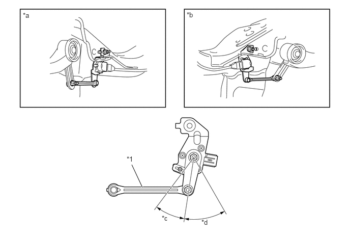
| *1 | Arm | - | - |
| *a | Rear Suspension LH | *b | Rear Suspension RH |
| *c | Bound | *d | Rebound |
Acceleration Sensor
The acceleration sensors detect the vertical movement above the body.
The acceleration sensors are placed on the right and left sides of the instrument panel. The acceleration sensors independently detect the vertical acceleration rate of the vehicle.
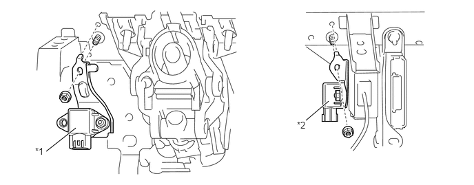
| *1 | Acceleration Sensor LH | *2 | Acceleration Sensor RH |
Steering Angle Sensor
A steering angle sensor is provided in the combination switch area. This sensor detects the amount of steering effort and the direction of steering wheel.
The sensor assembly contains 2 sets of magnetic reluctance elements that detect the rotational movement of a magnet that is built into the detection gear. Thus, the sensor detects the changes that occur in the magnetic reluctance elements along with the rotational movement of the detection gear, in order to detect the rotational movement of the steering wheel.
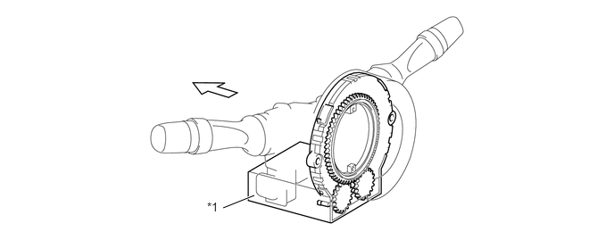
| *1 | Steering Angle Sensor | - | - |
Rear Air Suspension System Operation
General
The rear air suspension system effects the following controls:
| System Control | Outline | |
|---|---|---|
| Vehicle Height Control | Vehicle Height Switching Control | ·
The user can operate the height control switch to change the Normal vehicle height position to the HI or LO vehicle height position as needed. ·
The user can operate the height control switch to steplessly set the vehicle height to a desired position within the adjustable range. |
| Automatic Vehicle Height Control | Provides a function to keep a constant rear vehicle height regardless of the number of occupants or cargo. | |
| Vehicle Speed Sensing Control | When a vehicle height position other than Normal is selected and certain conditions have been met, the system automatically adjusts the position to the Normal vehicle height in order to attain optimal levels of driving stability and ride comfort. | |
| Key OFF Operation Control | For the purpose of making corrections such as when the rear vehicle height rises as a result of an occupant exiting the vehicle after the ignition switch has been turned OFF, this function effects control to lower the vehicle even after the ignition switch has been turned OFF. | |
| Vehicle Height Control OFF | This can be set by turning the height control mode select switch to the manual mode. | |
| Suspension Control | Normal Control | Shuts off the right and left pneumatic cylinders by closing the gate solenoid valve in order to ensure the proper rolling rigidity and stable driving |
| Off-road Control | Connects the right and left pneumatic cylinders by opening the gate solenoid valve in order to ensure the proper driving performance on very bumpy roads. | |
Vehicle Height Control
Vehicle Height Switching Control
In the auto mode, the user can operate the height control switch to change the Normal vehicle height to the HI vehicle height [+30 mm (+1.2 in.)] or the LO vehicle height [-30 mm (-1.2 in.)] as needed.
In the manual mode, the user can operate the height control switch to steplessly set the vehicle height to the desired position within the adjustable range.
Upon detecting the changes in the vehicle height through the signals from the height control sensor, the suspension control ECU blinks the selected vehicle height indicator light during the switching operation, and illuminates it after the operation has been completed.
| Vehicle Height | Specification |
|---|---|
|
*: Vehicle without added weight. |
|
| HI | +30 mm (+1.2 in.)/Approx. 25 sec.* |
| Normal | 0 |
| LO | -30 mm (-1.2 in.)/Approx. 35 sec.* |
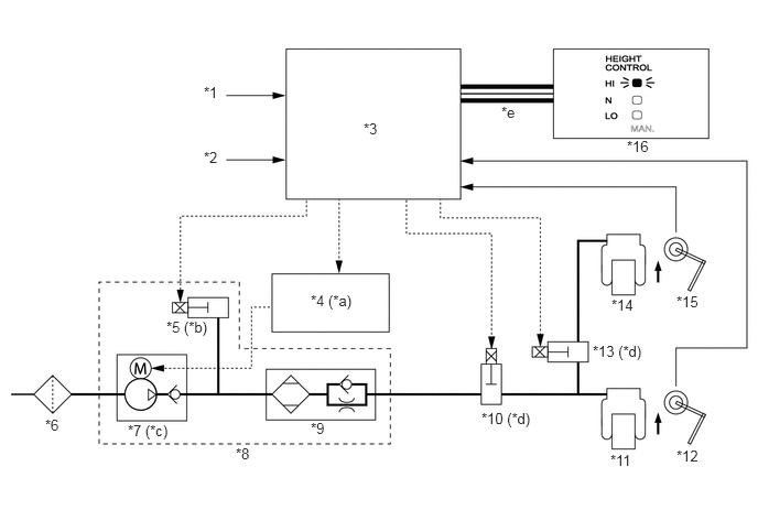
| *1 | Speed Sensor | *2 | Height Control Switch |
| *3 | Suspension Control ECU | *4 | Air Suspension Relay |
| *5 | Exhaust Solenoid Valve | *6 | Height Control Cleaner |
| *7 | Compressor and Motor | *8 | Compressor and Motor with Dryer |
| *9 | Dryer | *10 | Leveling Solenoid Valve |
| *11 | Pneumatic Cylinder LH | *12 | Height Control Sensor LH |
| *13 | Gate Solenoid Valve | *14 | Pneumatic Cylinder RH |
| *15 | Height Control Sensor RH | *16 | Combination Meter |
| *a | On | *b | On/Off (Open/Close) |
| *c | On (Actuate) | *d | On (Open) |
| *e | CAN (V1 Bus) | - | - |
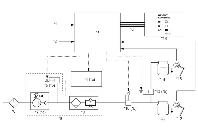
| *1 | Speed Sensor | *2 | Height Control Switch |
| *3 | Suspension Control ECU | *4 | Air Suspension Relay |
| *5 | Exhaust Solenoid Valve | *6 | Height Control Cleaner |
| *7 | Compressor and Motor | *8 | Compressor and Motor with Dryer |
| *9 | Dryer | *10 | Leveling Solenoid Valve |
| *11 | Pneumatic Cylinder LH | *12 | Height Control Sensor LH |
| *13 | Gate Solenoid Valve | *14 | Pneumatic Cylinder RH |
| *15 | Height Control Sensor RH | *16 | Combination Meter |
| *a | Off | *b | On (Open) |
| *c | Off (Stop) | *d | CAN (V1 Bus) |
Automatic Vehicle Height Control
The suspension control ECU detects via the 2 height control sensors the changes in the rear vehicle height that results from the number of occupants or the amount of the load. Then, the suspension control ECU controls the height control valve and the compressor and motor with dryer in order to automatically adjust the rear vehicle height to a constant (Normal) vehicle height.
If the vehicle height is lower than Normal, the suspension control ECU raises the vehicle height by turning ON (open) the exhaust solenoid valve, leveling solenoid valve, and gate solenoid valve, and actuating the compressor and motor with dryer. The exhaust solenoid valve remains ON (open) for a prescribed length of time (between 0 and 1 second) in order to ensure the initial operation of the compressor and motor with dryer and then turns OFF (closes). This length of the time is changed by power supply (+B) voltage.
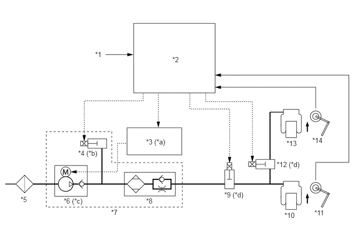
| *1 | Speed Sensor | *2 | Suspension Control ECU |
| *3 | Air Suspension Relay | *4 | Exhaust Solenoid Valve |
| *5 | Height Control Cleaner | *6 | Compressor and Motor |
| *7 | Compressor and Motor with Dryer | *8 | Dryer |
| *9 | Leveling Solenoid Valve | *10 | Pneumatic Cylinder LH |
| *11 | Height Control Sensor LH | *12 | Gate Solenoid Valve |
| *13 | Pneumatic Cylinder RH | *14 | Height Control Sensor RH |
| *a | On | *b | On/Off (Open/Close) |
| *c | On (Actuate) | *d | On (Open) |
If the vehicle height is higher than Normal, the suspension control ECU lowers the vehicle height by turning ON (open) the exhaust solenoid valve, leveling solenoid valve, and gate solenoid valve, and stopping the compressor and motor with dryer.
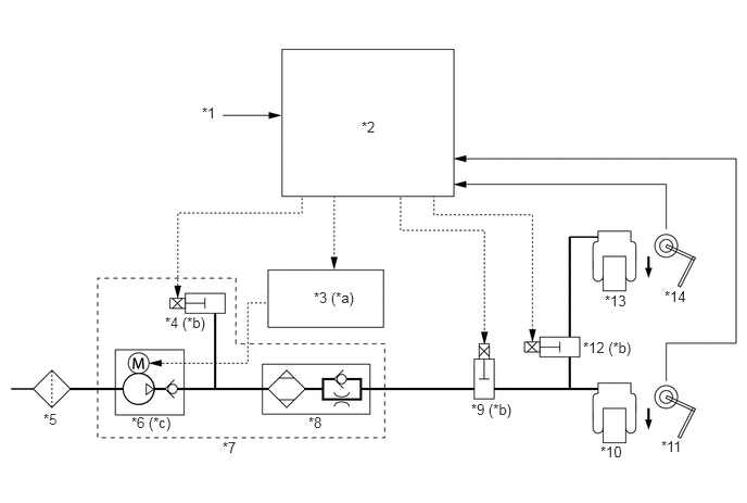
| *1 | Speed Sensor | *2 | Suspension Control ECU |
| *3 | Air Suspension Relay | *4 | Exhaust Solenoid Valve |
| *5 | Height Control Cleaner | *6 | Compressor and Motor |
| *7 | Compressor and Motor with Dryer | *8 | Dryer |
| *9 | Leveling Solenoid Valve | *10 | Pneumatic Cylinder LH |
| *11 | Height Control Sensor LH | *12 | Gate Solenoid Valve |
| *13 | Pneumatic Cylinder RH | *14 | Height Control Sensor RH |
| *a | Off | *b | On (Open) |
| *c | Off (Stop) | - | - |
Vehicle Speed Sensing Control
The suspension control ECU detects the vehicle speed through the signals provided by the front and rear speed sensors. When a vehicle height position other than Normal is selected and the conditions indicated in the table below have been met, the system automatically adjusts the position to the Normal vehicle height in order to attain optimal levels of driving stability and ride comfort. At this time, the suspension control ECU blinks the height control indicator (for Normal) and illuminates it after height control has been completed.
| Item | Mode | Vehicle Height | Specification |
|---|---|---|---|
| Vehicle Speed Sensing Control | Auto Mode | HI → Normal | more than 30 km/h (19 mph) |
| LO → Norma | more than 12 km/h (7 mph) | ||
| Manual Mode | LO and HI → Normal | more than 30 km/h (19 mph) |
Once the vehicle is adjusted to the Normal vehicle height through this control, it is not possible to select a vehicle height by operating the height control switch at a prescribed vehicle speed or below, unless the initial control is effected again.
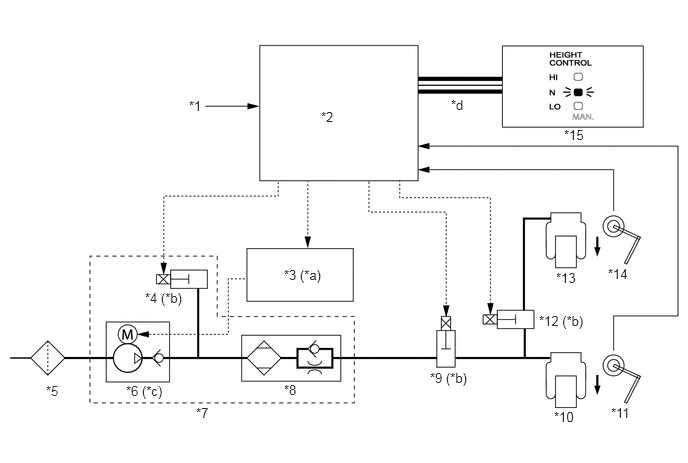
| *1 | Speed Sensor | *2 | Suspension Control ECU |
| *3 | Air Suspension Relay | *4 | Exhaust Solenoid Valve |
| *5 | Height Control Cleaner | *6 | Compressor and Motor |
| *7 | Compressor and Motor with Dryer | *8 | Dryer |
| *9 | Leveling Solenoid Valve | *10 | Pneumatic Cylinder LH |
| *11 | Height Control Sensor LH | *12 | Gate Solenoid Valve |
| *13 | Pneumatic Cylinder RH | *14 | Height Control Sensor RH |
| *15 | Combination Meter | - | - |
| *a | Off | *b | On (Open) |
| *c | Off (Stop) | *d | CAN (V1 Bus) |
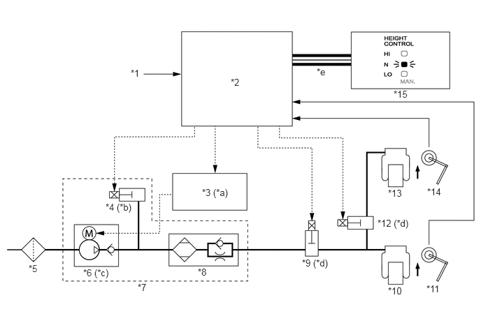
| *1 | Speed Sensor | *2 | Suspension Control ECU |
| *3 | Air Suspension Relay | *4 | Exhaust Solenoid Valve |
| *5 | Height Control Cleaner | *6 | Compressor and Motor |
| *7 | Compressor and Motor with Dryer | *8 | Dryer |
| *9 | Leveling Solenoid Valve | *10 | Pneumatic Cylinder LH |
| *11 | Height Control Sensor LH | *12 | Gate Solenoid Valve |
| *13 | Pneumatic Cylinder RH | *14 | Height Control Sensor RH |
| *15 | Combination Meter | - | - |
| *a | On | *b | On/Off (Open/Close) |
| *c | On (Actuate) | *d | On (Open) |
| *e | CAN (V1 Bus) | - | - |
Key OFF Operation Control
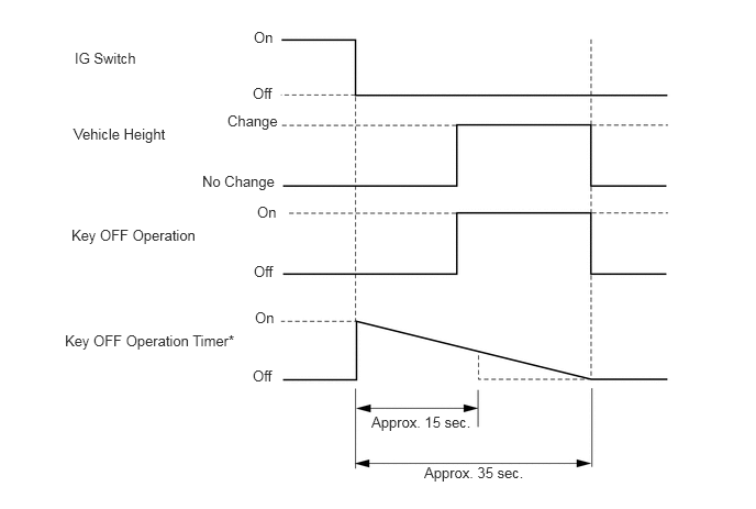
If the vehicle height increases after an occupant exits the vehicle or a cargo is unloaded when the ignition key is OFF, this control causes the vehicle to resume the target vehicle height only for a prescribed length of time.
The suspension control ECU detects the OFF signal through the ignition switch, the door open/close signal from the 5 door courtesy switches, and the vehicle height condition from the 2 height control sensor, in order to effect the key OFF operation control as shown in the timing chart below.
There are 2 types of key OFF operation time depending on the vehicle height condition.
| Vehicle Height Condition | Key OFF Operation Time |
|---|---|
| No change | Approx. 15 sec. |
| Change | Approx. 35 sec. |
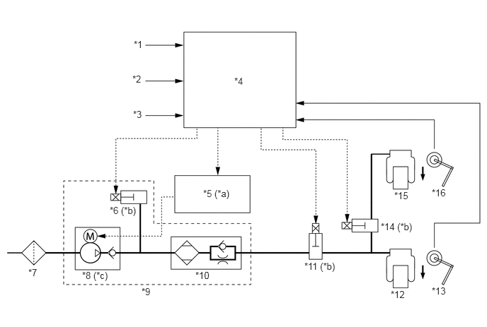
| *1 | Door Courtesy Switch | *2 | Back Door Courtesy Switch |
| *3 | Ignition Switch | *4 | Suspension Control ECU |
| *5 | Air Suspension Relay | *6 | Exhaust Solenoid Valve |
| *7 | Height Control Cleaner | *8 | Compressor and Motor |
| *9 | Compressor and Motor with Dryer | *10 | Dryer |
| *11 | Leveling Solenoid Valve | *12 | Pneumatic Cylinder LH |
| *13 | Height Control Sensor LH | *14 | Gate Solenoid Valve |
| *15 | Pneumatic Cylinder RH | *16 | Height Control Sensor RH |
| *a | Off | *b | On (Open) |
| *c | Off (Stop) | - | - |
Vehicle Height Control OFF
Turning the height control mode select switch to select the manual mode causes the automatic vehicle height control to stop. This prevents unexpected changes in vehicle height or the inability of effecting normal control caused by raising the vehicle on a jack or hitching a trailer.
When the vehicle height control is in the manual mode, the height control manual indicator light in the combination meter illuminates.
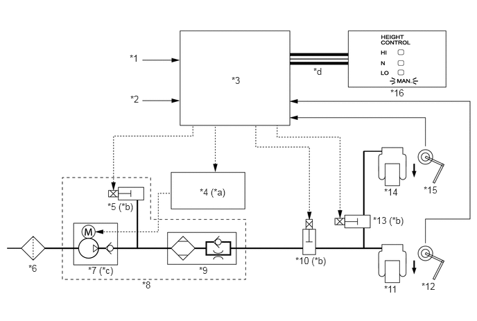
| *1 | Height Control Mode Select Switch | *2 | Speed Sensor |
| *3 | Suspension Control ECU | *4 | Air Suspension Relay |
| *5 | Exhaust Solenoid Valve | *6 | Height Control Cleaner |
| *7 | Compressor and Motor | *8 | Compressor and Motor with Dryer |
| *9 | Dryer | *10 | Leveling Solenoid Valve |
| *11 | Pneumatic Cylinder LH | *12 | Height Control Sensor LH |
| *13 | Gate Solenoid Valve | *14 | Pneumatic Cylinder RH |
| *15 | Height Control Sensor RH | *16 | Combination Meter |
| *a | Off | *b | Off (Close) |
| *c | Off (Stop) | *d | CAN (V1 Bus) |
Suspension Control
General
The suspension control consists of a normal control and an off-road control.
The normal control turns OFF (close) the gate solenoid valve during normal driving in order to increase the vehicle's rolling rigidity and ensure stability.
The off-road control turns ON (open) the gate solenoid valve while the vehicle is being driven on bumpy roads at low speeds in order to ensure the proper driving performance.
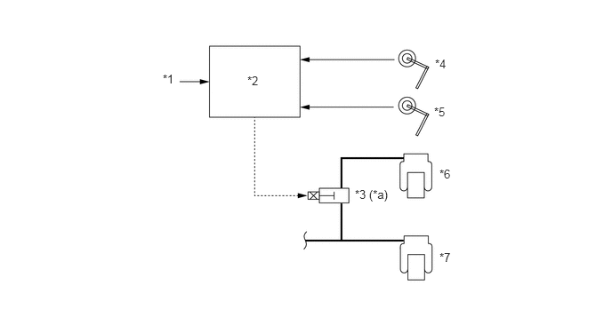
| *1 | Speed Sensor | *2 | Suspension Control ECU |
| *3 | Gate Solenoid Valve | *4 | Height Control Sensor RH |
| *5 | Height Control Sensor RH | *6 | Pneumatic Cylinder LH |
| *7 | Pneumatic Cylinder LH | - | - |
| *a | On (Open) / Off (Close) | - | - |
Normal Control
Upon detecting the vehicle speed through the signals from the speed sensors, and the vehicle height through the signals from the height control sensors, the suspension control ECU turns OFF (close) the gate solenoid valve in order to shut off the air path between the right and left pneumatic cylinders.
Off-road Control
The suspension control ECU determines when to start off-road control based on the height position signal and vehicle speed signal.
The suspension control ECU starts off-road control when the vehicle speed is below 20 km/h (12 mph) and the vehicle height difference between the right and left sides is 100 mm (3.9 in.) or more.
When the off-road control starts, the gate solenoid valve opens, causing the rear roll rigidity to decrease. When the negative phase is input, the suspension stroke increases in order to enhance the grip of the tires, thus improving the driving performance of the vehicle.
When the suspension control ECU detects a vehicle speed of 20 km/h (12 mph) or more, it closes the gate solenoid valve and cancels the off-road control.
Diagnosis
If the suspension control ECU detects a malfunction in the rear air suspension system, it blinks the height control manual indicator light to alert the driver of the malfunction. The suspension control ECU will also store a DTC (Diagnostic Trouble Code). The DTC can be accessed through the blinking of the height control manual indicator light by connecting the SST (09843-18040) between the TC and CG terminals of DLC3 or the use of a Techstream.
For details, refer to the Repair Manual.
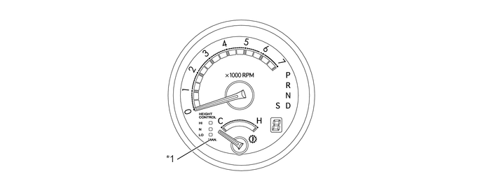
| *1 | Height Control Manual Indicator Light | - | - |
Fail-safe
If a malfunction occurs in any of the sensors or actuator, the suspension control ECU prohibits the vehicle height control.
AVS System Operation
General
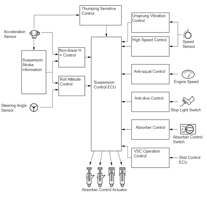
The AVS system effects the following controls:
| System Control | Outline |
|---|---|
| Non-linear H∞ Control | Smoothly changes the damping force to a target value in accordance with the changes in the road surface or driving conditions. Thus, excellent ride comfort has been realized while ensuring a high level of vibration damping performance. |
| Thumping Sensitive Control | When the road surface condition does not require a damping force, this function controls the shock absorbers so that their damping force will not increase. |
| Unsprung Vibration Control | If unsprung resonance is detected, this function controls so that the damping force will not decrease below a certain level, in order to reduce the unsprung resonance. |
| Roll Attitude Control | Regulates the damping force to reduce the phase difference between the vehicle roll and pitch angles during steering, thus providing smooth superior maneuverability. |
| Anti-dive Control | During braking, this function makes the damping force firmer to restrain the body dive, thus ensuring excellent stability and controllability. |
| Anti-squat Control | During acceleration, this function makes the damping force firmer to minimize the changes in the vehicle body posture. |
| High Speed Control | This function varies the variable range of the damping force according to vehicle speed in order to realize a soft and comfortable ride and a stable driving condition.The damping force is controlled at a softer variable range at low speeds, and at a firmer variable range at high speeds. |
| Absorber Control | The absorber control switch enables the driver to select a desired damping force from the 3 modes. |
| VSC Operation Control | Changes the damping force to control the vehicle posture during VSC operation (front or rear skid). As a result, road-holding performance has been realized during VSC operation. |
The suspension control ECU receives signals from the sensors and switches to control the absorber control actuators. Thus, it optimally controls the damping force in accordance with the driving conditions and road conditions.
Non-linear H∞ Control
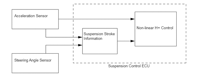
The non-linear H∞ control smoothly changes the damping force to a target value in accordance with the changes in the road surface or driving conditions. Thus, excellent ride comfort has been realized while ensuring a high level of vibration damping performance.
To effect this control, the suspension stroke information is calculated based on the sprung acceleration rate from the 2 acceleration sensors and the information from the steering angle sensor. Thus, the driving conditions of the vehicle are detected.
Roll Attitude Control
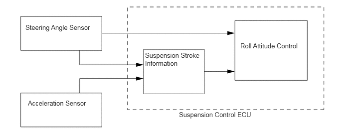
The roll attitude control Regulates the damping force to reduce the phase difference between the vehicle roll and pitch angles during steering, thus providing smooth superior maneuverability. This control assumes that 2 types of shock absorbers (1 for restraining roll and the other for restraining lift) are provided at an imaginary point on inside of the turn of the vehicle. The function of these shock absorbers is to prevent the center of gravity of the vehicle from rising. The damping force of the front and rear shock absorbers is controlled in order to control the vehicle's posture as in this imaginary condition.

| *a | For Restraining Roll | *b | For Restraining Lift |
| *c | Center of Gravity | - | - |
To effect this control, the suspension stroke information is calculated based on the information from the 2 acceleration sensors and a steering angle sensor. Thus, the driving conditions of the vehicle are detected.
Diagnosis
If the suspension control ECU detects a malfunction in the AVS system, it will store a DTC (Diagnostic Trouble Code). The DTC can be accessed through the blinking of the height control manual indicator light by connecting the SST (09843-18040) between the TC and CG terminals of DLC3 or the use of a Techstream.
For details, refer to the Repair Manual.
| *1 | Height Control Manual Indicator Light | - | - |
Fail-safe
If a malfunction occurs in any of the sensors or actuators, the suspension control ECU prohibits the damping force control.