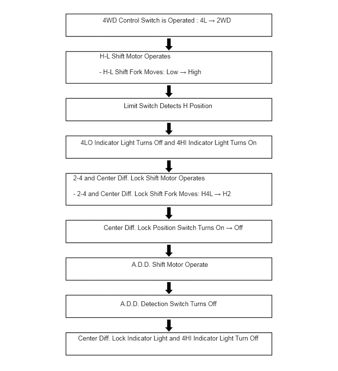
CHASSIS TRANSFER GENERAL/CONTROL/DETAILS 4WD CONTROL SYSTEM
General
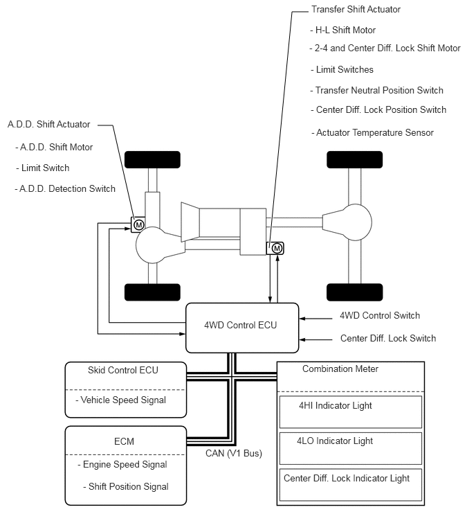
The 4WD system allows the driver to select the appropriate mode from among the 5 drive modes by utilizing the 4WD control switch and center differential lock switch. In addition, the Automatic Disconnecting Differential (A.D.D.) operates after the center differential lock position switch in the transfer shift actuator turns on.
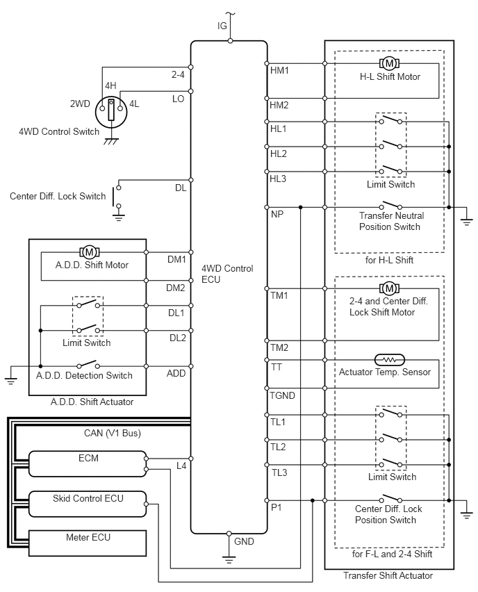
Through these switch signals, the 4WD control ECU actuates the 2 shift motors in the transfer shift actuator and the shift motor in the A.D.D. shift actuator.
System Diagram
Wiring Diagram
Layout of Main Components
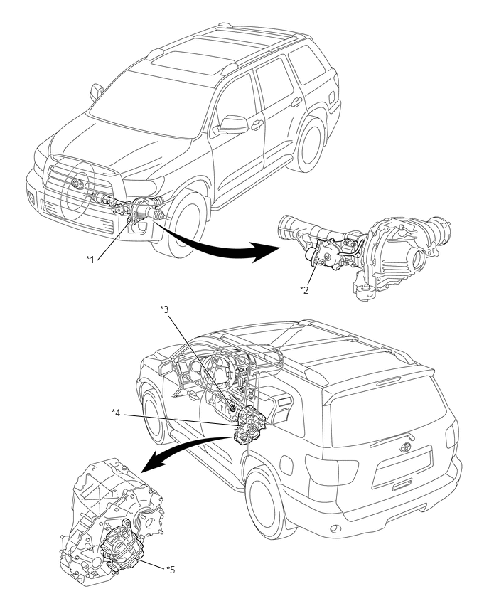
| *1 | Front Differential | *2 | A.D.D. Shift Actuator
·
A.D.D. Shift Motor ·
Limit Switch ·
A.D.D. Detection Switch |
| *3 | Park/Neutral Position Switch | *4 | Transfer |
| *5 | Transfer Shift Actuator
·
H-L Shift Motor ·
2-4 and Center Diff. Lock Shift Motor ·
Limit Switch ·
Transfer Neutral Position Switch ·
Center Diff. Lock Position Switch ·
Actuator Temperature Sensor |
- | - |
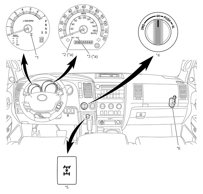
| *1 | Center Diff. Lock Indicator Light | *2 | 4HI Indicator Light |
| *3 | 4LO Indicator Light | *4 | 4WD Control Switch |
| *5 | Center Diff. Lock Switch | *6 | 4WD Control ECU |
| *a | Displayed at this position on the SR5 grade only. | - | - |
System Operation
General
The 4WD mode switching pattern of this system is as shown in the illustration below:
When the vehicle speed is below approximately 100 km/h (62 mph)*, free-lock and 2WD-4WD switching (switching patterns A to G) is available while the vehicle is running.
When the 4WD control ECU detects that the 4WD control switch is operated with a mode switching restriction condition satisfied, it prohibits shifting and informs the driver by flashing the 4HI indicator light and sounding the buzzer in the combination meter.
The high-low switching of the transfer gear ratio (switching patterns H to M) is available only when the vehicle is stationary and the shift position is N.
*: If the air temperature is below -15°C (5°F), the mode can be switched from 2WD to 4WD when the vehicle speed is below 70 km/h (43 mph).
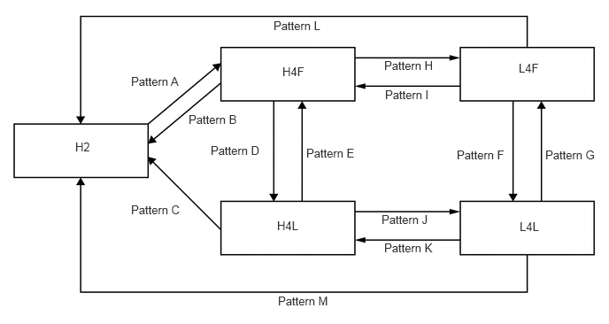
H2: High Speed 2WD
H4F: High Speed 4WD and Center Differential Free
H4L: High Speed 4WD and Center Differential Lock
L4F: Low Speed 4WD and Center Differential Free
L4L: Low Speed 4WD and Center Differential Lock
Switching Pattern: A (H2 → H4F)
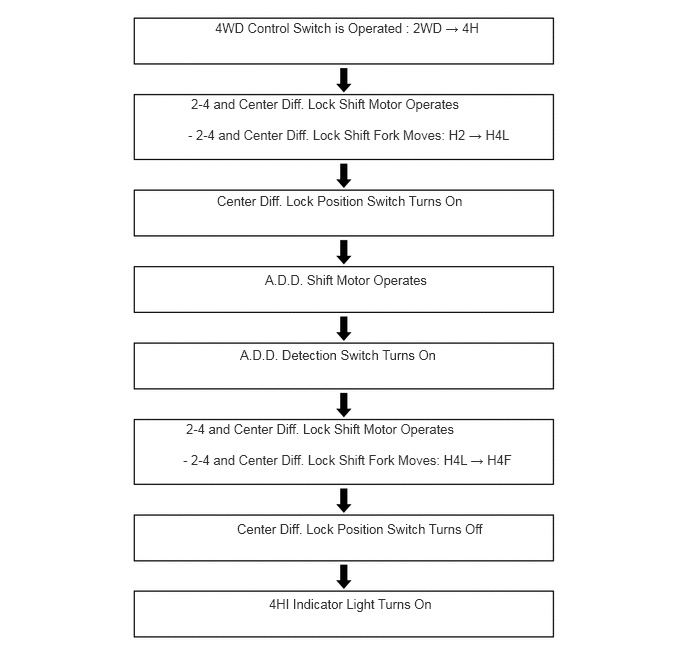
In H2 mode, when the 4WD control switch is turned from the 2WD to 4H position, the 4WD control ECU actuates the 2-4 and center differential lock shift motor to move the 2-4 and center differential lock shift fork shaft to the right. Simultaneously, the 2-4 and center differential lock shift fork shaft moves to the right together with the 2-4 and center differential lock shift fork. As a result, the front drive clutch sleeve engages the center differential case, transfer clutch hub and transfer drive sprocket. Thus, the mode changes to H4L.
The 4WD control ECU detects the state of the center differential through the limit switch and the center differential lock position switch.
The A.D.D. shift actuator operates to effect the 4WD mode.
The 2-4 and center differential lock shift motor moves the 2-4 and center differential lock shift fork shaft further to the right. At this time, the 2-4 and center differential lock shift fork shaft moves further to the right together with the 2-4 and center differential lock shift fork. As a result, the front drive clutch sleeve disengages the center differential case, and engages the transfer clutch hub and the transfer drive sprocket. Thus, the mode changes to H4F.
The 4WD control ECU detects the state of the center differential through the limit switch and the center differential lock position switch. The 4HI indicator light turns on after switching from H2 to H4F mode has been completed.
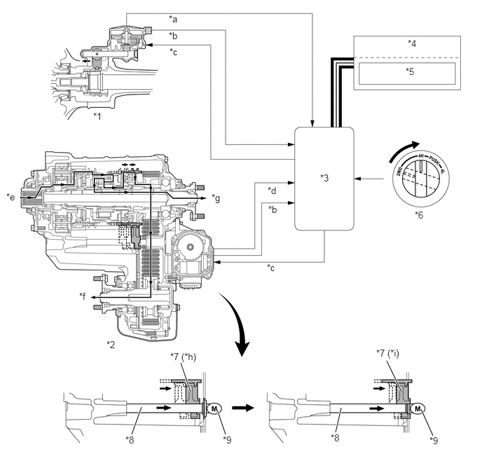
| *1 | Front Differential | *2 | Transfer |
| *3 | 4WD Control ECU | *4 | Combination Meter |
| *5 | 4HI Indicator Light | *6 | 4WD Control Switch |
| *7 | 2-4 and Center Diff. Lock Shift Fork | *8 | 2-4 and Center Diff. Lock Shift Fork Shaft |
| *9 | 2-4 and Center Diff. Lock Shift Motor | - | - |
| *a | A.D.D. Detection Switch Signal | *b | Limit Switch Signal |
| *c | Motor Actuate Signal | *d | Center Diff. Lock Position Switch Signal |
| *e | Input | *f | Front Output |
| *g | Rear Output | *h | H2 Position → H4L Position |
| *i | H4L Position → H4F Position | - | - |
Switching Pattern: B (H4F → H2)
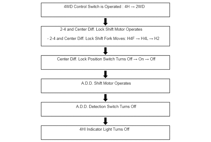
In H4F mode, when the 4WD control switch is turned from the 4H to 2WD position, the 4WD control ECU actuates the 2-4 and center differential lock shift motor to move the 2-4 and center differential lock shift fork shaft to the left (to the far left position passing over H4L). Simultaneously, the 2-4 and center differential lock shift fork shaft moves to the left (to the far left position passing over H4L) together with the 2-4 and center differential lock shift fork. As a result, the front drive clutch sleeve disengages the transfer drive sprocket, and engages the center differential case and the transfer clutch hub. Thus, the mode changes to H2.
The 4WD control ECU detects the state of the center differential through the limit switch and the center differential lock position switch.
The A.D.D. shift actuator operates to effect the 2WD mode. The 4HI indicator light turns off after switching from H4F to H2 mode has been completed.
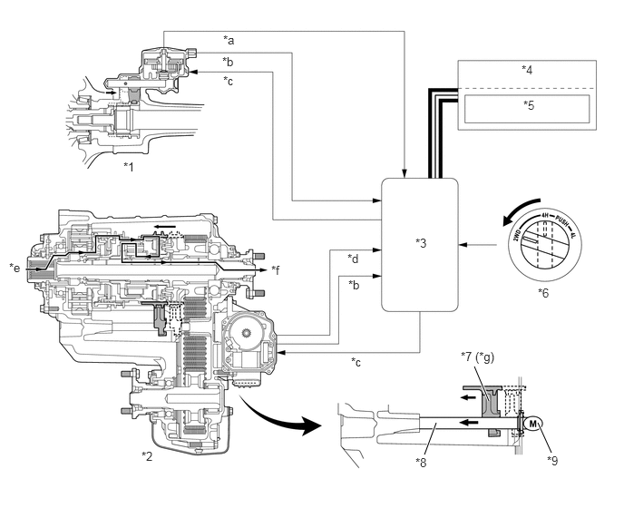
| *1 | Front Differential | *2 | Transfer |
| *3 | 4WD Control ECU | *4 | Combination Meter |
| *5 | 4HI Indicator Light | *6 | 4WD Control Switch |
| *7 | 2-4 and Center Diff. Lock Shift Fork | *8 | 2-4 and Center Diff. Lock Shift Fork Shaft |
| *9 | 2-4 and Center Diff. Lock Shift Motor | - | - |
| *a | A.D.D. Detection Switch Signal | *b | Limit Switch Signal |
| *c | Motor Actuate Signal | *d | Center Diff. Lock Position Switch Signal |
| *e | Input | *f | Rear Output |
| *g | H4F Position → H4L Position → H2 Position | - | - |
Switching Pattern: C (H4L → H2)
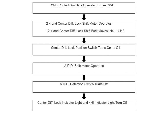
In H4L mode, when the 4WD control switch is turned from the 4L to 2WD position, the 4WD control ECU actuates the 2-4 and center differential lock shift motor to move the 2-4 and center differential lock shift fork shaft to the left. Simultaneously, the 2-4 and center differential lock shift fork shaft moves to the left together with the 2-4 and center differential lock shift fork. As a result, the front drive clutch sleeve disengages the transfer drive sprocket, and engages the center differential case and the transfer clutch hub. Thus, the mode changes to H2.
The 4WD control ECU detects the state of the center differential through the limit switch and the center differential lock position switch.
The A.D.D. shift actuator operates to effect the 2WD mode. The 4HI indicator light and the center differential lock indicator light turn off after switching from H4L to H2 mode has been completed.
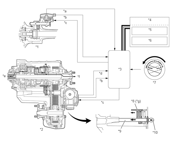
| *1 | Front Differential | *2 | Transfer |
| *3 | 4WD Control ECU | *4 | Combination Meter |
| *5 | 4HI Indicator Light | *6 | Center Diff. Lock Indicator Light |
| *7 | 4WD Control Switch | *8 | 2-4 and Center Diff. Lock Shift Fork |
| *9 | 2-4 and Center Diff. Lock Shift Motor | *10 | 2-4 and Center Diff. Lock Shift Motor |
| *a | A.D.D. Detection Switch Signal | *b | Limit Switch Signal |
| *c | Motor Actuate Signal | *d | Center Diff. Lock Position Switch Signal |
| *e | Input | *f | Rear Output |
| *g | H4L Position → H2 Position | - | - |
Switching Pattern D (H4F → H4L)
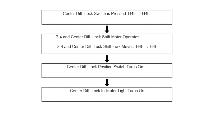
In H4F mode, when the center differential lock switch is turned ON, the 4WD control ECU actuates the 2-4 and center differential lock shift motor to move the 2-4 and center differential lock shift fork shaft to the left. Simultaneously, the 2-4 and center differential lock shift fork shaft moves to the left together with the 2-4 and center differential lock shift fork. As a result, the front drive clutch sleeve engages the center differential case, transfer clutch hub and transfer drive sprocket. Thus, the mode changes to H4L.
The 4WD control ECU detects the state of the center differential through the limit switch and the center differential lock position switch. The 4WD control ECU causes the center differential lock indicator light to turn on when the center differential is locked.
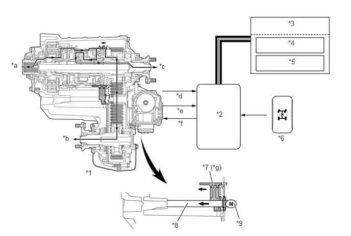
| *1 | Transfer | *2 | 4WD Control ECU |
| *3 | Combination Meter | *4 | 4HI Indicator Light |
| *5 | Center Diff. Lock Indicator Light | *6 | Center Diff. Lock Switch |
| *7 | 2-4 and Center Diff. Lock Shift Fork | *8 | 2-4 and Center Diff. Lock Shift Fork Shaft |
| *9 | 2-4 and Center Diff. Lock Shift Motor | - | - |
| *a | Input | *b | Front Output |
| *c | Rear Output | *d | Center Diff. Lock Position Switch Signal |
| *e | Limit Switch Signal | *f | Motor Actuate Signal |
| *g | H4F Position → H4L Position | - | - |
Switching Pattern E (H4L → H4F)
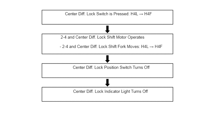
In H4L mode, when the center differential lock switch is turned off, the 4WD control ECU actuates the 2-4 and center differential lock shift motor to move the 2-4 and center differential lock shift fork shaft to the right. Simultaneously, the 2-4 and center differential lock shift fork shaft moves to the right together with the 2-4 and center differential lock shift fork. As a result, the front drive clutch sleeve disengages the center differential case, and engages the transfer clutch hub and the transfer drive sprocket. Thus, the mode changes to H4F.
The 4WD control ECU detects the state of the center differential through the limit switch and the center differential lock position switch. The 4WD control ECU causes the center differential lock indicator light to turn off when the center differential is unlocked.
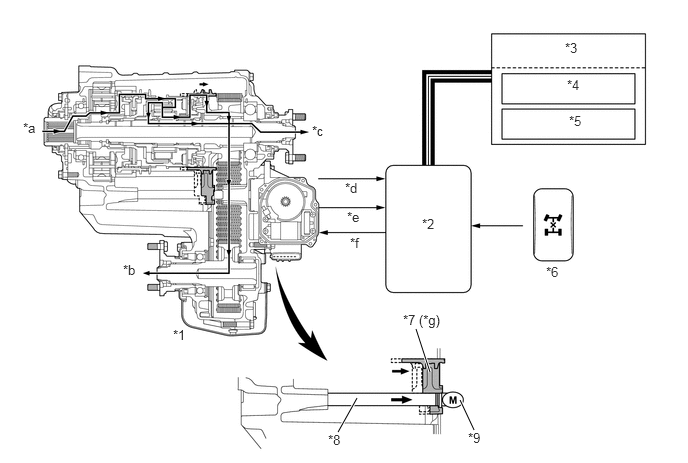
| *1 | Transfer | *2 | 4WD Control ECU |
| *3 | Combination Meter | *4 | 4HI Indicator Light |
| *5 | Center Diff. Lock Indicator Light | *6 | Center Diff. Lock Switch |
| *7 | 2-4 and Center Diff. Lock Shift Fork | *8 | 2-4 and Center Diff. Lock Shift Fork Shaft |
| *9 | 2-4 and Center Diff. Lock Shift Motor | - | - |
| *a | Input | *b | Front Output |
| *c | Rear Output | *d | Center Diff. Lock Position Switch Signal |
| *e | Limit Switch Signal | *f | Motor Actuate Signal |
| *g | H4L Position →H4F Position | - | - |
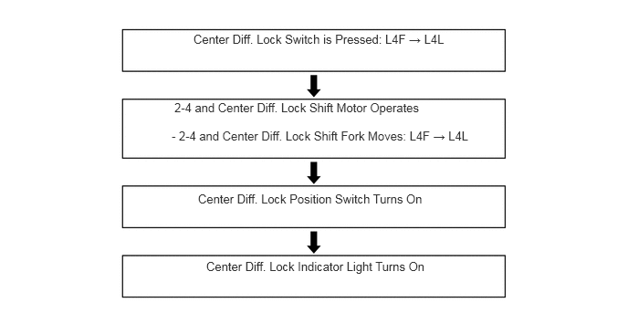
Switching Pattern F (L4F → L4L)
In L4F mode, when the center differential lock switch is turned ON, the 4WD control ECU actuates the 2-4 and center differential lock shift motor to move the 2-4 and center differential lock shift fork shaft to the left. Simultaneously, the 2-4 and center differential lock shift fork shaft moves to the left together with the 2-4 and center differential lock shift fork. As a result, the front drive clutch sleeve engages the center differential case, transfer clutch hub and transfer drive sprocket. Thus, the mode changes to L4L.
The 4WD control ECU detects the state of the center differential through the limit switch and the center differential lock position switch. The 4WD control ECU causes the center differential lock indicator light to turn on when the center differential is locked.
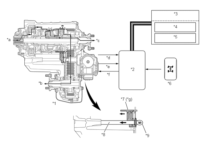
| *1 | Transfer | *2 | 4WD Control ECU |
| *3 | Combination Meter | *4 | 4LO Indicator Light |
| *5 | Center Diff. Lock Indicator Light | *6 | Center Diff. Lock Switch |
| *7 | 2-4 and Center Diff. Lock Shift Fork | *8 | 2-4 and Center Diff. Lock Shift Fork Shaft |
| *9 | 2-4 and Center Diff. Lock Shift Motor | - | - |
| *a | Input | *b | Front Output |
| *c | Rear Output | *d | Center Diff. Lock Position Switch Signal |
| *e | Limit Switch Signal | *f | Motor Actuate Signal |
| *g | L4F Position → L4L Position | - | - |
Switching Pattern G (L4L → L4F)
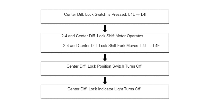
In L4L mode, when the center differential lock switch is turned off, the 4WD control ECU actuates the 2-4 and center differential lock shift motor to move the 2-4 and center differential lock shift fork shaft to the right. Simultaneously, the 2-4 and center differential lock shift fork shaft moves to the right together with the 2-4 and center differential lock shift fork. As a result, the front drive clutch sleeve disengages the center differential case, and engages the transfer clutch hub and the transfer drive sprocket. Thus, the mode changes to L4F.
The 4WD control ECU detects the state of the center differential through the limit switch and the center differential lock position switch. The 4WD control ECU causes the center differential lock indicator light to turn off when the center differential is unlocked.
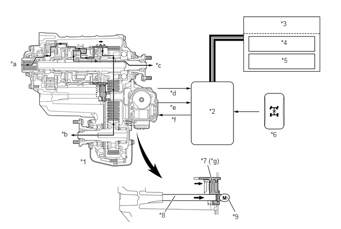
| *1 | Transfer | *2 | 4WD Control ECU |
| *3 | Combination Meter | *4 | 4LO Indicator Light |
| *5 | Center Diff. Lock Indicator Light | *6 | Center Diff. Lock Switch |
| *7 | 2-4 and Center Diff. Lock Shift Fork | *8 | 2-4 and Center Diff. Lock Shift Fork Shaft |
| *9 | 2-4 and Center Diff. Lock Shift Motor | - | - |
| *a | Input | *b | Front Output |
| *c | Rear Output | *d | Center Diff. Lock Position Switch Signal |
| *e | Limit Switch Signal | *f | Motor Actuate Signal |
| *g | L4L Position → L4F Position | - | - |
Switching Pattern H (H4F → L4F)
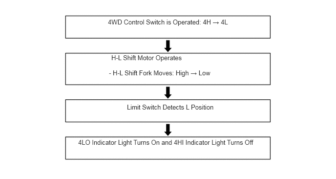
In H4F mode, when the 4WD control switch is turned from the 4H to 4L position, the 4WD control ECU actuates the H-L shift motor to move the H-L shift fork shaft to the right. Simultaneously, the H-L shift fork shaft moves to the right together with the H-L shift fork. As a result, the transfer high and low clutch sleeve of the planetary gear unit engages the planetary spline piece. Thus, the mode changes to L4F.
The 4WD control ECU detects the state of the H-L position through the limit switch and the transfer neutral position switch. The 4WD control ECU causes the 4LO indicator light to turn on and the 4HI indicator light to turn off when switching to the L4F mode has been completed.
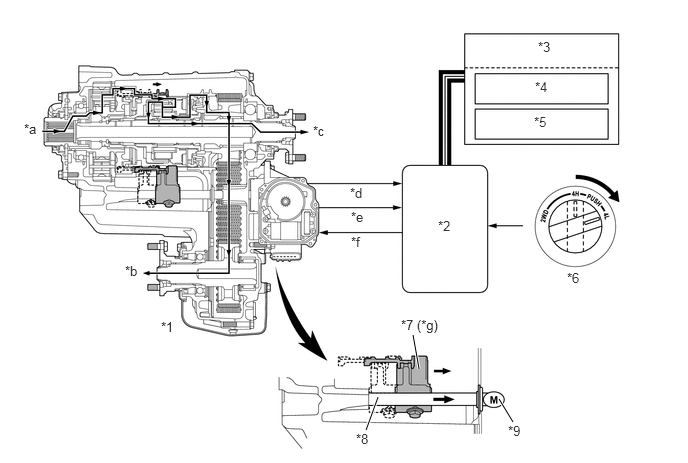
| *1 | Transfer | *2 | 4WD Control ECU |
| *3 | Combination Meter | *4 | 4HI Indicator Light |
| *5 | 4LO Indicator Light | *6 | 4WD Control Switch |
| *7 | H-L Shift Fork | *8 | H-L Shift Fork Shaft |
| *9 | H-L Shift Motor | - | - |
| *a | Input | *b | Front Output |
| *c | Rear Output | *d | Transfer Neutral Position Switch Signal |
| *e | Limit Switch Signal | *f | Motor Actuate Signal |
| *g | Low Position → High Position | - | - |
Switching Pattern I (L4F → H4F)
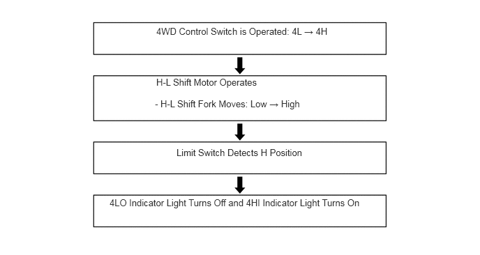
In L4F mode, when the 4WD control switch is turned from the 4L to 4H position, the 4WD control ECU actuates the H-L shift motor to move the H-L shift fork shaft to the left. Simultaneously, the H-L shift fork shaft moves to the left together with the H-L shift fork. As a result, the transfer high and low clutch sleeve of the planetary gear unit engages the transfer high piece. Thus, the mode changes to H4F.
The 4WD control ECU detects the state of the H-L position through the limit switch and the transfer neutral position switch. The 4WD control ECU causes the 4LO indicator light to turn off and the 4HI indicator light to turn on when switching to the H4F mode has been completed.
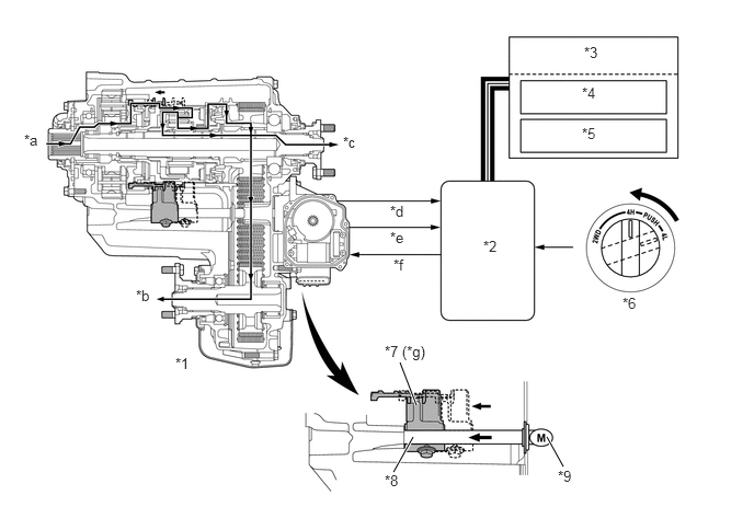
| *1 | Transfer | *2 | 4WD Control ECU |
| *3 | Combination Meter | *4 | 4HI Indicator Light |
| *5 | 4LO Indicator Light | *6 | 4WD Control Switch |
| *7 | H-L Shift Fork | *8 | H-L Shift Fork Shaft |
| *9 | H-L Shift Motor | - | - |
| *a | Input | *b | Front Output |
| *c | Rear Output | *d | Transfer Neutral Position Switch Signal |
| *e | Limit Switch Signal | *f | Motor Actuate Signal |
| *g | Low Position → High Position | - | - |
Switching Pattern J (H4L → L4L)
In H4L mode, when the 4WD control switch is turned from the 4H to 4L position, the 4WD control ECU actuates the H-L shift motor to move the H-L shift fork shaft to the right. Simultaneously, the H-L shift fork shaft moves to the right together with the H-L shift fork. As a result, the high and low clutch sleeve of the planetary gear unit engages the planetary spline piece. Thus, the mode changes to L4L.
The 4WD control ECU detects the state of the H-L position through the limit switch and the transfer neutral position switch. The 4WD control ECU causes the 4LO indicator light to turn on and the 4HI indicator light to turn off when switching to the L4L mode has been completed.
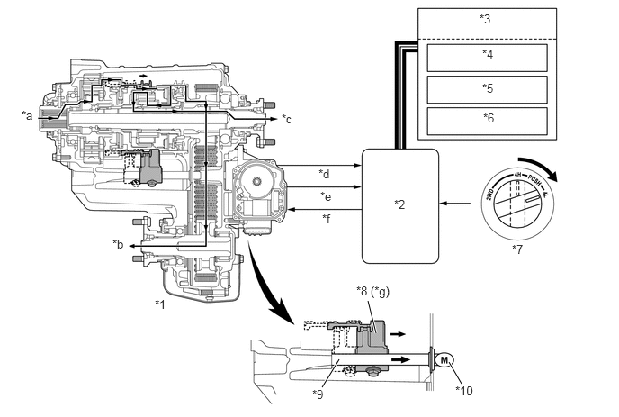
| *1 | Transfer | *2 | 4WD Control ECU |
| *3 | Combination Meter | *4 | 4HI Indicator Light |
| *5 | 4LO Indicator Light | *6 | Center Diff. Lock Indicator Light |
| *7 | 4WD Control Switch | *8 | H-L Shift Fork |
| *9 | H-L Shift Fork Shaft | *10 | H-L Shift Motor |
| *a | Input | *b | Front Output |
| *c | Rear Output | *d | Transfer Neutral Position Switch Signal |
| *e | Limit Switch Signal | *f | Motor Actuate Signal |
| *g | High Position → Low Position | - | - |
Switching Pattern K (L4L → H4L)
In L4L mode, when the 4WD control switch is turned from the 4L to 4H position, the 4WD control ECU actuates the H-L shift motor to move the H-L shift fork shaft to the left. Simultaneously, the H-L shift fork shaft moves to the left together with the H-L shift fork. As a result, the high and low clutch sleeve of the planetary gear unit engages the transfer high piece. Thus, the mode changes to H4L.
The 4WD control ECU detects the state of the H-L position through the limit switch and the transfer neutral position switch. The 4WD control ECU causes the 4LO indicator light to turn off and the 4HI indicator light to turn on when switching to the H4L mode has been completed.
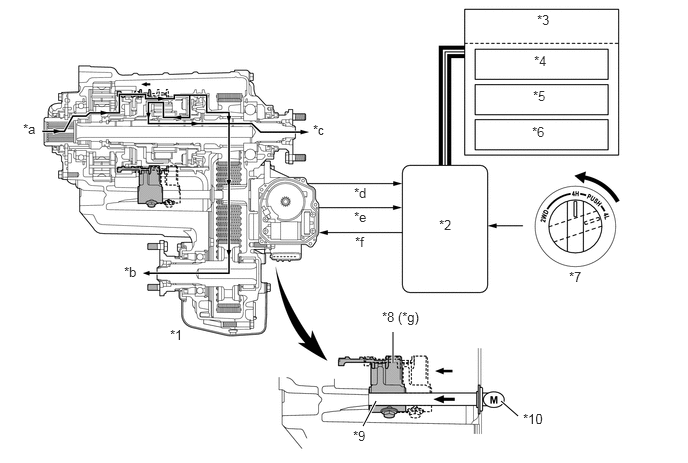
| *1 | Transfer | *2 | 4WD Control ECU |
| *3 | Combination Meter | *4 | 4HI Indicator Light |
| *5 | 4LO Indicator Light | *6 | Center Diff. Lock Indicator Light |
| *7 | 4WD Control Switch | *8 | H-L Shift Fork |
| *9 | H-L Shift Fork Shaft | *10 | H-L Shift Motor |
| *a | Input | *b | Front Output |
| *c | Rear Output | *d | Transfer Neutral Position Switch Signal |
| *e | Limit Switch Signal | *f | Motor Actuate Signal |
| *g | Low Position → High Position | - | - |
Switching Pattern L (L4F → H2)
In L4F mode, when the 4WD control switch is turned from the 4L to 2WD position, the 4WD control ECU actuates the transfer and A.D.D. shift motors. The switching operation changes in the following sequence: L4F → H4F → H2 (switching pattern I → B).
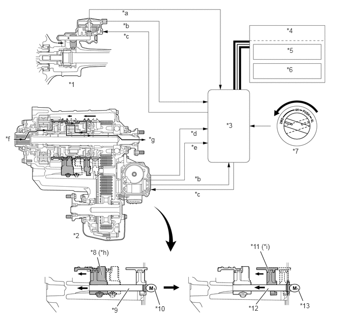
| *1 | Front Differential | *2 | Transfer |
| *3 | 4WD Control ECU | *4 | Combination Meter |
| *5 | 4HI Indicator Light | *6 | 4LO Indicator Light |
| *7 | 4WD Control Switch | *8 | H-L Shift Fork |
| *9 | H-L Shift Fork Shaft | *10 | H-L Shift Motor |
| *11 | 2-4 and Center Diff. Lock Shift Fork | *12 | 2-4 and Center Diff. Lock Shift Fork Shaft |
| *13 | 2-4 and Center Diff. Lock Shift Motor | - | - |
| *a | A.D.D. Detection Switch Signal | *b | Limit Switch Signal |
| *c | Motor Actuate Signal | *d | Center Diff. Lock Position Switch Signal |
| *e | Transfer Neutral Position Switch Signal | *f | Input |
| *g | Rear Output | *h | Low Position → High Position |
| *i | H4F Position → H2 Position | - | - |
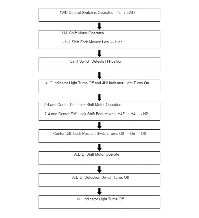
Switching Pattern M (L4L → H2)
In L4L mode, when the 4WD control switch is turned from the 4L to 2WD position, the 4WD control ECU actuates the transfer and A.D.D. shift motors. The switching operation changes in the following sequence: L4L → H4L → H2 (switching pattern K → C).
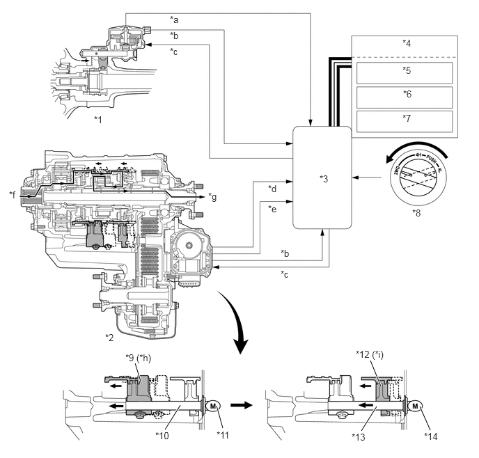
| *1 | Front Differential | *2 | Transfer |
| *3 | 4WD Control ECU | *4 | Combination Meter |
| *5 | 4HI Indicator Light | *6 | 4LO Indicator Light |
| *7 | Center Diff. Lock Indicator Light | *8 | 4WD Control Switch |
| *9 | H-L Shift Fork | *10 | H-L Shift Fork Shaft |
| *11 | H-L Shift Motor | *12 | 2-4 and Center Diff. Lock Shift Fork |
| *13 | 2-4 and Center Diff. Lock Shift Fork Shaft | *14 | 2-4 and Center Diff. Lock Shift Motor |
| *a | A.D.D. Detection Switch Signal | *b | Limit Switch Signal |
| *c | Motor Actuate Signal | *d | Center Diff. Lock Position Switch Signal |
| *e | Transfer Neutral Position Switch Signal | *f | Input |
| *g | Rear Output | *h | Low Position → High Position |
| *i | H4L Position → H2 Position | - | - |