BODY ELECTRICAL BLIND SPOT MONITOR SYSTEM GENERAL/CONTROL/DETAILS CONSTRUCTION AND OPERATION
GENERAL
The blind spot monitor system operates when both of the following conditions are met:
The warning cancel switch assembly is on.
The vehicle speed is greater than approximately 32 km/h (20 mph).
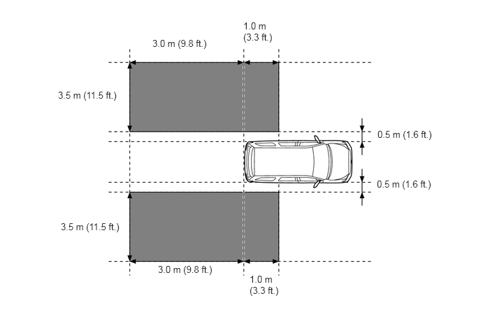
The blind spot monitor system can detect vehicles in its blind spot detection areas.
The blind spot detection areas formed by the blind spot monitor sensors LH and RH are as shown below:
The driver's vehicle is overtaken by another vehicle in the adjacent lane.
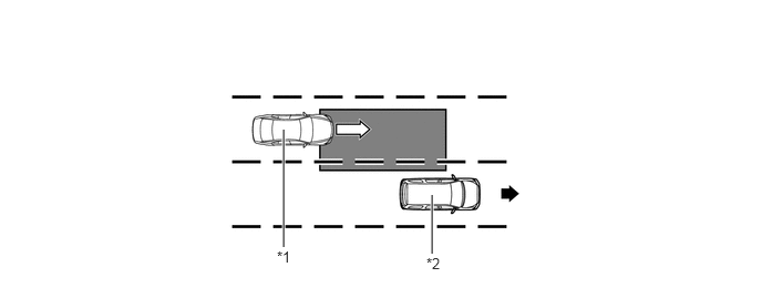
| *1 | Other Vehicle | *2 | Driver's Vehicle |

|
Speed of other vehicle | 
|
Speed of driver's vehicle |

|
Blind spot detection area | - | - |
When another vehicle enters the blind spot detection area of the driver's vehicle due to a lane change.
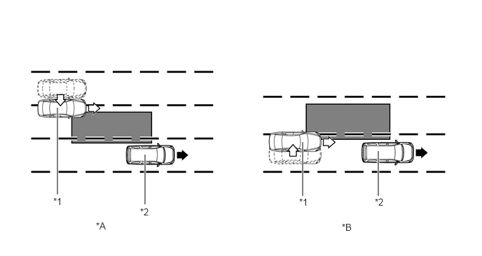
| *A | The other vehicle enters the detection area during lane change (merge in) (Type 1). | *B | The other vehicle enters the detection area during lane change (merge in) (Type 2). |
| *1 | Other Vehicle | *2 | Driver's Vehicle |
|
|
Speed of other vehicle |
|
Speed of driver's vehicle |
|
|
Blind spot detection area | - | - |
BLIND SPOT MONITOR SENSOR
The blind spot monitor sensor consists of a millimeter wave radar circuit and a signal processing circuit.
The millimeter wave radar uses frequencies in the 24 GHz band.
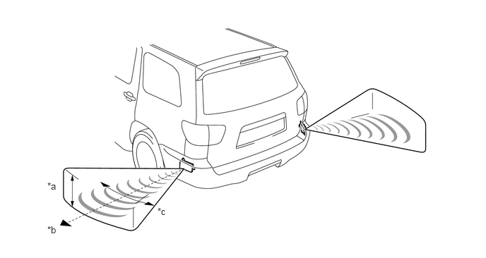
| *a | Approx. 20° | *b | Approx. 10 m (33 ft.) |
| *c | Approx. 150° | - | - |
The distance to the object, azimuth and relative speed are calculated from the information that is provided by the reflected millimeter wave radar as described below:
| Item | Calculation Method |
|---|---|
|
*: The Doppler effect causes the observer to perceive the radio waves emitted by a moving object to be a higher frequency as it approaches, and to be a lower frequency as it recedes. This phenomenon is created because when an object is located far away, the radio waves are perceived at higher frequencies than those of the radio source. An SST is used if radar axis confirmation is needed. For details, refer to the Sequoia Repair Manual. |
|
| Distance | Calculated from the length of time that has elapsed from the time the waves of the millimeter wave radar have been emitted, until the reflected waves are received by the millimeter wave radar circuit. The detection distance is approx. 10 m (33 ft.). |
| Azimuth | Calculated from the reception angle of the millimeter wave radar reflections received. The detection angle has a horizontal range of approx. 150° and a vertical range of approx. 20°. |
| Relative Speed | Calculated by utilizing the change (Doppler effect*) that occurs in the frequency of the reflected millimeter wave radar waves. |
In accordance with operation conditions, the blind spot monitor system promotes safety confirmation by using the blind spot monitor indicator to inform the driver that another vehicle has entered the blind spot monitor sensor detection area of the driver's vehicle.
The blind spot monitor indicator informs the driver that a vehicle is present in the blind spot detection area by illuminating when the turn signal switch is not operated, and by flashing when a vehicle is present and the turn signal switch is operated.
COMBINATION METER ASSEMBLY
The combination meter assembly is provided with the multi-information display to inform the driver of a malfunction in the blind spot monitor system.
Two types of warning messages are used for the blind spot monitor system, as described below. The blind spot monitor system will not operate when these messages appear in the combination meter assembly.
| Multi-information Display | Detail |
|---|---|
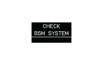
|
This message appears when the blind spot monitor sensor detects a system malfunction. |
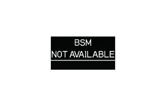
|
This message appears when the blind spot monitor sensor determines the following conditions:
·
Dirty blind spot monitor sensor ·
Poor weather condition ·
Significantly high or low outside temperatures After these conditions have been eliminated, the system will operate normally. |
DIAGNOSIS
The blind spot monitor system is equipped with a diagnosis function which can display the multi-information display in the combination meter assembly. For details, refer to the Sequoia Service Bulletin.