BODY ELECTRICAL AIR CONDITIONING GENERAL/CONTROL/DETAILS CONSTRUCTION AND OPERATION
Heater Control Panel
Front Heater Control Panel
An electric heater control panel is used.
The front heater control panel has large switches and knobs, improving ease of use and visibility.

Rear Heater Control Panel
The set temperature for rear seats and the operation mode for the rear air conditioning can be adjusted by individually operating the switches arranged on the rear heater control panel located behind the center console.
The set temperature for the rear air conditioning zone is displayed on the Liquid Crystal Display (LCD) of the rear heater control panel.

Front Air Conditioning Unit
General
A semi-centrally located air conditioning unit, in which the evaporator and heater radiator are mounted transversely, is used. As a result, the air conditioning unit is made compact and lightweight.
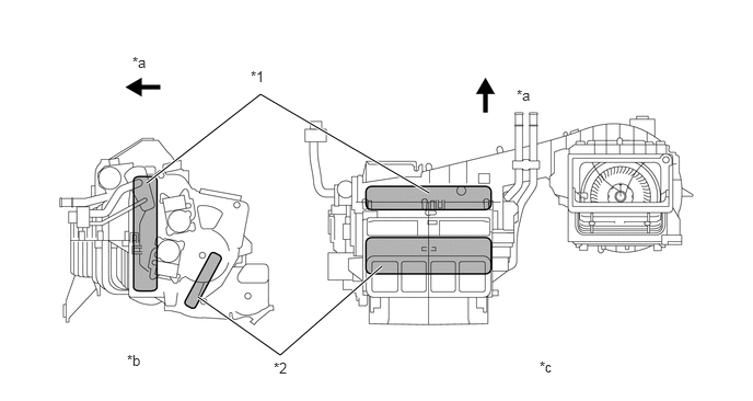
| *1 | Evaporator | *2 | Heater Radiator |
| *a | Front | *b | Side View |
| *c | Top View | - | - |
Evaporator
A Revolutionary super-slim Structure (RS) type evaporator is used. Placing the tanks at the top and the bottom of the evaporator and using a micropore tube construction have achieved the following effects:
The heat exchange efficiency is improved.
The temperature distribution is made more uniform.
The evaporator is made thinner, from 90 mm (3.5 in.) to 50 mm (2.0 in.).
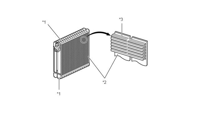
| *1 | Tank | *2 | Micropore Tube |
| *3 | Cooling Fin | - | - |
Evaporator Temperature Sensor
The evaporator temperature sensor detects the temperature of the cool air immediately past the evaporator in the form of resistance changes, and outputs it to the air conditioning amplifier.
Heater Radiator
A compact, lightweight, and highly efficient Straight Flow Aluminum (SFA)-II type heater radiator is used.

Blower Motor
The blower motor has a built-in blower controller, and is controlled using duty control performed by the air conditioning amplifier.
Bus Connector
A bus connector is used in the wire harness connection that connects the servomotor from the air conditioning amplifier.
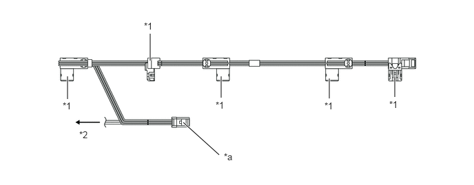
| *1 | Bus Connector | *2 | Evaporator Temperature Sensor |
| *a | To Air Conditioning Amplifier | - | - |
The bus connector has a built-in communication/driver IC which communicates with each servomotor connector, actuates the servomotor, and has a position detection function. This enables bus communication for the servomotor wire harness to achieve a more lightweight construction and a reduced number of wires.
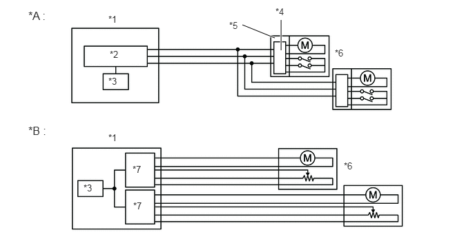
| *A | With Bus Connector | *B | Without Bus Connector |
| *1 | Air Conditioning Amplifier | *2 | Communication IC |
| *3 | CPU | *4 | Communication/Driver IC |
| *5 | Bus Connector | *6 | Servomotor |
| *7 | Driver IC | - | - |
Servomotor
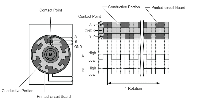
The pulse pattern type servomotor consists of a printed circuit board and a servomotor. The printed circuit board has 3 contact points, and can transmit 2 kinds of on-off signals to the air conditioning amplifier based on the difference of the pulse phases. The bus connector can detect the damper position and movement direction with this signal.
Clean Air Filter
A pollen removal type air refiner element is used to remove dust, pollen, and other micron particles from air entering from outside the vehicle to provide a comfortable cabin of clean air.
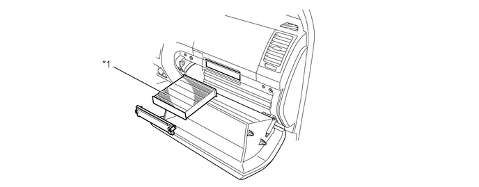
| *1 | Clean Air Filter | - | - |
Rear Air Conditioning Unit
The rear air conditioning unit is located in the right quarter trim.
The rear air conditioning unit consists of the evaporator, heater radiator, air mix servomotor, mode control servomotor, evaporator temperature sensor, rear blower controller and rear blower motor.
The evaporator and heater radiator are arranged horizontally to allow the airflow to be directed smoothly upward.
The mode control servomotor operates the laminate sliding type mode control door, and the air mix servomotor controls the full air mix type air mix doors.
The evaporator has the same Revolutionary super-slim Structure (RS) as the front evaporator. For details regarding the evaporator.
The heater radiator has the same Straight Flow Aluminum (SFA)-II type as the front heater radiator. For details regarding the heater radiator.
The evaporator temperature sensor detects the temperature of the cool air immediately past the evaporator in the form of resistance changes, and outputs it to the air conditioning amplifier.
As in the front air conditioning unit, the servomotor fitted to the rear air conditioning unit is connected to the air conditioning amplifier with the bus connector due to the lightweight construction and a reduced number of wires. For details regarding the bus connector. Furthermore, the pulse pattern type is used for both the front and rear air conditioning units. For details regarding the servomotor.
The porous duct excellent in sound absorption property is provided in the air inlet duct to improve quietness in the cabin. The cross section of the porous duct consists of 3 layers. The inner polyethyleneterephtalate layer absorbs noises produced by the air conditioning unit, the central layer prevents the leakage of odor in the cabin, and the outer felt holds the duct shape.
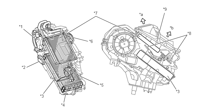
| *1 | Blower Motor | *2 | Rear Blower Controller |
| *3 | Evaporator | *4 | Rear Evaporator Temp. Sensor |
| *5 | Air Mix Servomotor | *6 | Mode Control Servomotor |
| *7 | Heater Radiator | *8 | Air Mix Door |
| *9 | Mode Control Door (Laminate Sliding Type) | - | - |
| *a | Foot | *b | Face |
Condenser
A Multi-Flow (MF) type condenser is used. The condenser consists of 3 portions: a condensing portion, a super-cooling portion, and a gas-liquid separator (modulator) are integrated together. This condenser uses a sub-cool cycle that offers excellent heat-exchange performance.
In the sub-cool cycle, after the refrigerant passes through the condensing portion of the condenser, both the liquid refrigerant and the gaseous refrigerant that could not be liquefied are cooled again in the super-cooling portion. Thus, the refrigerant is sent to the evaporator in an almost completely liquefied state.
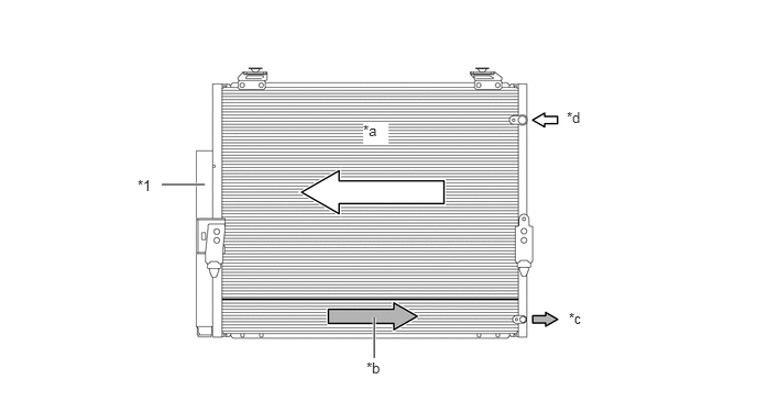
| *1 | Modulator | - | - |
| *a | Condensing Portion | *b | Super-cooling Portion |
| *c | Liquid Refrigerant | *d | Gaseous Refrigerant |
- HINT:
-
The point at which the air bubbles disappear in the refrigerant of the sub-cool cycle is lower than the proper amount of refrigerant with which the system must be filled. Therefore, if the system is recharged with refrigerant based on the point at which the air bubbles disappear, the amount of refrigerant would be insufficient. As a result, the cooling performance of the system would be affected. If the system is overcharged with refrigerant, this will also lead to reduced performance. For the proper method of verifying the amount of the refrigerant and for instructions on how to recharge the system with refrigerant, refer to the Repair Manual.
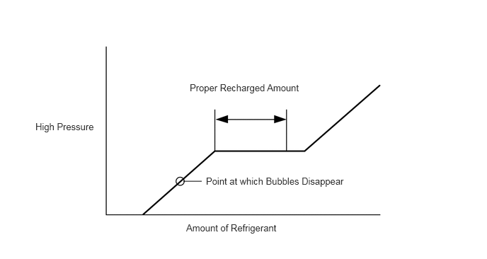 2.698,2.667 2.969,2.667 false 0.521,1.781 1.542,2.135 1.021,0.354 10 false High Pressure 2.792,1.208 4.552,1.604 1.76,0.396 10 false Proper Recharged Amount 3.031,2.583 5.302,2.99 2.271,0.406 10 false Point at which Bubbles Disappear 2.74,3.271 4.188,3.688 1.448,0.417 10 false Amount of Refrigerant
A/C Compressor
General
A 10SR19C A/C compressor has been provided, which features a compact, lightweight and low-noise swash plate design.
The A/C compressor consists of the A/C pulley, shaft, lug plate, swash plate, piston, shoe, crank chamber, cylinder, and lock sensor.
The lock sensor sends an A/C compressor speed signal to the ECM. The ECM compares this signal with an engine speed signal sent from the crankshaft position sensor. If the ECM determines that the A/C pulley has locked, the ECM turns the magnetic clutch off.
A rotary valve capable of directing suction refrigerant into the cylinder has been provided.
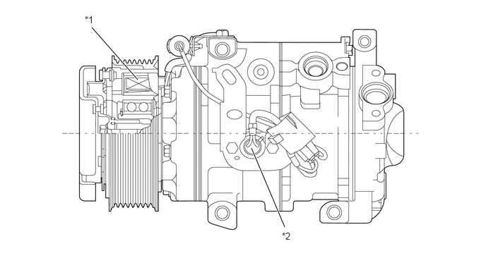
| *1 | Pulley with Magnetic Clutch | *2 | Lock Sensor |
Rotary Valve
In order to eliminate suction loss, the rotary valve has been replaced with a conventional suction valve.
A hollow shaft is used in the valve so as to allow refrigerant to be sucked into the compressing section of the cylinder through the hollow section. Holes individually arranged on the shaft and cylinder are designed to align during the rotation of the shaft. When the holes are aligned, refrigerant is sucked into the compressing section.
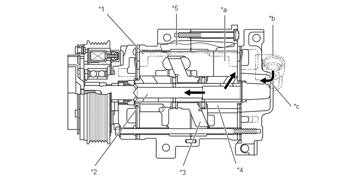
| *1 | Piston | *2 | Shaft |
| *3 | Lug Plate | *4 | Housing |
| *5 | Cylinder | - | - |
| *a | Compressing Section | *b | Suction Section |
| *c | Refrigerant Flow | - | - |
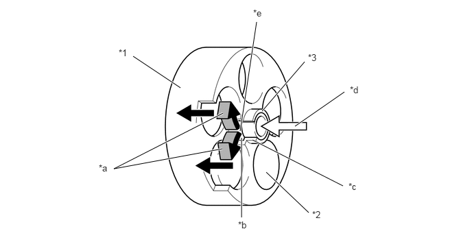
| *1 | Cylinder | *2 | Cylinder Bore |
| *3 | Shaft | - | - |
| *a | Refrigerant Flow | *b | The Position where the Rotary Valve Suction Port and Cylinder Suction Passage Become Aligned |
| *c | Cylinder Suction Passage | *d | Refrigerant Flow |
| *e | Rotary Valve Suction Port | - | - |
Sub-cool Accelerator (Double-pipe Internal Heat Exchanger) System
General
A sub-cool accelerator (double-pipe internal heat exchanger) system has been provided. This system consists of an inner pipe and an outer pipe which are changed from the conventional refrigerant pipes (liquid and gaseous refrigerant pipes).
The cooling performance can be enhanced by occurring heat exchange by utilizing temperature difference of refrigerant in a refrigeration cycle and further cooling the refrigerant discharged from the condenser.
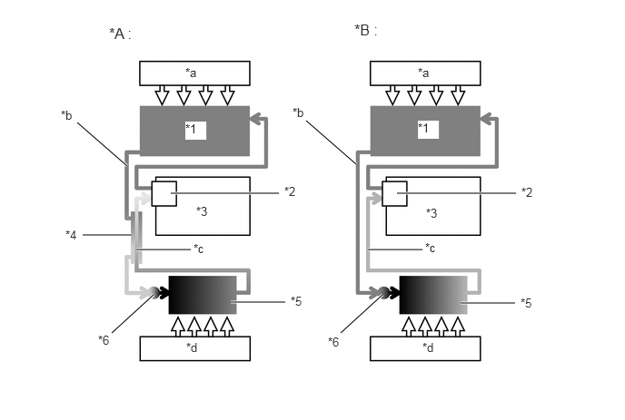
| *A | New Model | *B | Conventional |
| *1 | Condenser | *2 | Compressor |
| *3 | Engine | *4 | Sub-cool Accelerator System |
| *5 | Evaporator | *6 | Expansion Valve |
| *a | Outside Air | *b | High-temperature, High-pressure Liquid Refrigerant |
| *c | Low-temperature,Low-pressure Gaseous Refrigerant | *d | Inside Air |
Refrigerant Pipe
The refrigerant pipe consists of inner and outer pipes, and thus heat exchange can occur by utilizing the temperature difference between low-temperature, low-pressure gaseous refrigerant flowing inside the inner pipe and high-temperature, high-pressure liquid refrigerant flowing between the inner and outer pipes. Furthermore, a spiral groove is formed in the pipe in order to attain further effective heat exchange.
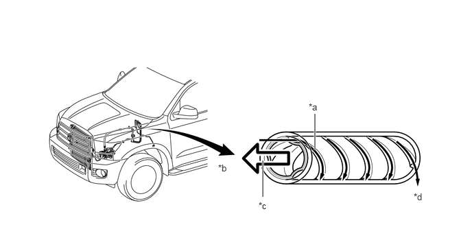
| *a | High-temperature, High-pressure Liquid Refrigerant | *b | To Compressor and Condenser |
| *c | Low-temperature, Low-pressure Gaseous Refrigerant | *d | To Evaporator |
A/C Pressure Sensor
The A/C pressure sensor detects the refrigerant pressure and outputs it to the air conditioning amplifier in the form of voltage changes.
Room Temperature Sensor
The room temperature sensor detects the room temperature based on changes in the resistance of its built-in thermistor. This signal is used by the air conditioning amplifier.
Ambient Temperature Sensor
The ambient temperature sensor detects the outside temperature based on changes in the resistance of its built-in thermistor. This signal is used by the air conditioning amplifier.
Solar Sensor
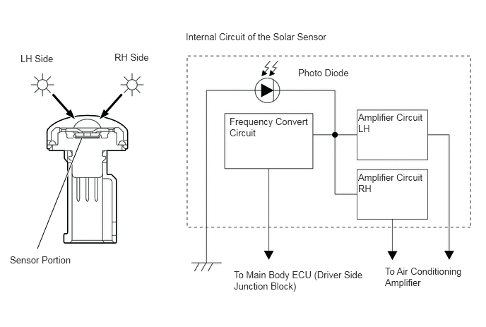
The solar sensor consists of a photo diode, 2 amplifier circuits for the solar sensor, and a frequency converter circuit for the light control sensor.
The solar sensor detects (in the form of changes in the current that flows through the built-in photo diode) the changes in the amount of sunlight from its LH and RH sides (2 directions) and outputs these sunlight strength signals to the air conditioning amplifier.