BODY ELECTRICAL DYNAMIC LASER CRUISE CONTROL SYSTEM GENERAL/CONTROL/DETAILS CONSTRUCTION AND OPERATION
CRUISE CONTROL SWITCH
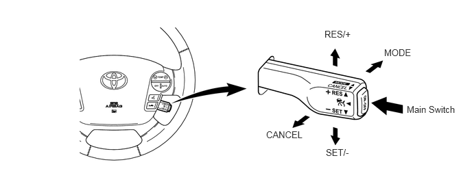
The cruise control switch consists of the main, RES/+, MODE, SET/- and CANCEL switches. The RES/+, MODE, SET/- and CANCEL switches are a lever that operates in four directions.
The cruise control switch is an automatic reset (normally open) type that turns ON only when the switch is being operated and turns OFF as soon as the driver releases the switch. Furthermore, the functions of the control switch are active only when the cruise control system has been turned ON using the main switch on the cruise control switch.
DISTANCE CONTROL SWITCH
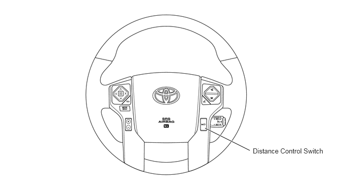
While the vehicle is being driven in vehicle-to-vehicle distance control mode, the vehicle-to-vehicle distance setting can be changed each time the distance control switch is pressed, as follows; long → middle → short.
If the ignition switch is turned OFF and back to ON, the system will default to "long".
The vehicle-to-vehicle distance is set as follows:
|
*: While driving at a vehicle speed of 90 km/h (55 mph). |
|
| Mode | Vehicle-to-vehicle Distance* |
| Long | Approx. 75 m (240 ft.) |
| Middle | Approx. 50 m (160 ft.) |
| Short | Approx. 30 m (105 ft.) |
COMBINATION METER
The combination meter provides a master warning light, CRUISE main indicator light, buzzer, and multi-information display to warn and indicate in the dynamic laser cruise control system.
The multi-information display indicates information such as the set speed, the constant speed control mode, the vehicle-to-vehicle distance, the presence of a vehicle ahead, and the warning message.
Examples of the illumination or display of the indicator light, warning light or multi-information display are shown below.
| Mode | Condition | Multi-information Display | CRUSE Main Indicator Light | Master Warning Light | Buzzer |
|---|---|---|---|---|---|
| Constant Speed Control | Being Controlled | 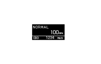
|
Illuminate | - | - |
| Vehicle-to-Vehicle Distance Control | Set Standby | 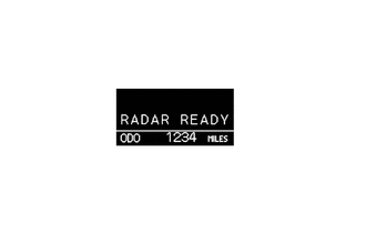
|
Illuminate | - | - |
| Under ConstantSpeed Control (No Vehicle Ahead) | 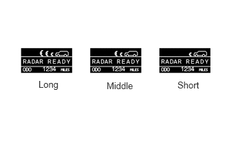
0.583,1.198 1.073,1.604
0.49,0.406
10
false
Long
1.615,1.219 2.219,1.615
0.604,0.396
10
false
Middle
2.688,1.208 3.177,1.635
0.49,0.427
10
false
Short
|
Illuminate | - | - | |
| Under Follow-up Control (Vehicle Ahead) | 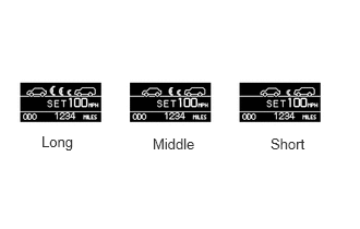
0.396,1.271 0.875,1.615
0.479,0.344
10
false
Long
1.458,1.292 2.031,1.635
0.573,0.344
10
false
Middle
2.583,1.292 3.156,1.719
0.573,0.427
10
false
Short
|
Illuminate | - | - | |
| Deceleration Control (Vehicle Ahead) | 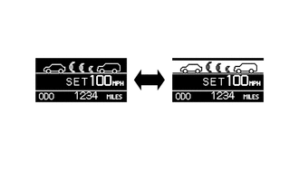
Flashes display frame, ahead vehicle and indication between. |
Illuminate | - | Sounds Continuously | |
| System Failure | Laser radar sensor is dirty. | 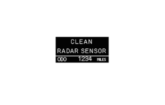
|
Flash | Illuminate | Sounds Once |
| Poor Weather Condition | 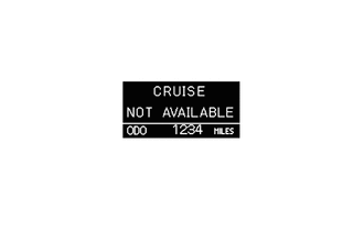
|
Flash | Illuminate | Sounds Once | |
| System Check* | 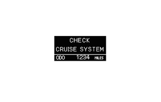
|
Flash | Illuminate | Sounds Once | |
| Beam Axis Adjustment | 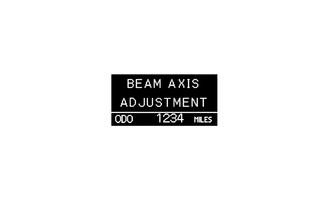
|
Flash | - | - | |
LASER RADAR SENSOR
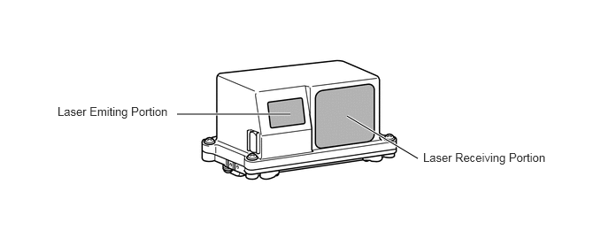
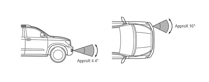
The laser radar sensor contains the laser emitting portion, laser receiving portion, and CPU. The laser beams that are output by the laser emitting portion are radiated forward. Then, the laser beams are reflected by the reflectors of the vehicle that is driven ahead. The length of time the reflected beams return to the laser receiving portion is calculated by the CPU. This is to determine the distance to the vehicle ahead and calculate the relative speed. These data are then transmitted to the distance control ECU. This sensor is designed so that it does not react to non-moving objects.
- HINT:
-
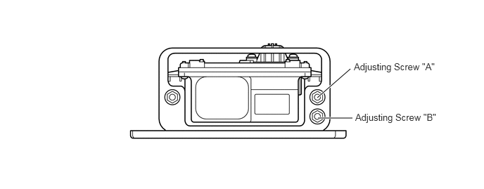
After a laser radar sensor has been replaced or removed and reinstalled, Techstream must be used to adjust the sensor angle. To ensure the proper precision, the sensor must be adjusted in the horizontal and vertical state. For this reason, the sensor is provided with an area for placing level, as well as the adjusting screws "A" and "B". For details, refer to the Repair Manual.