RM27L0U
_51
Engine / Hybrid System
_049300
3UR-FE EMISSION CONTROL
_0235597
PURGE VALVE
G
3UR-FE EMISSION CONTROL PURGE VALVE INSPECTION
PROCEDURE

 25860
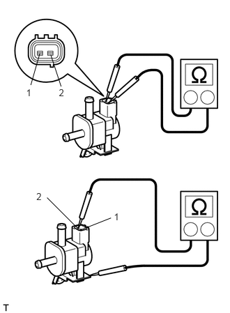
1.INSPECT NO. 1 VACUUM SWITCHING VALVE ASSEMBLY
0.391,1.307 0.543,1.475
0.152,0.169
10
1
0.88,1.307 1.033,1.475
0.152,0.169
10
2
1.703,3.16 1.855,3.329
0.152,0.169
10
1
0.544,2.852 0.696,3.021
0.152,0.169
10
2
0.595,0.797 0.46,1.27
false
0.758,0.819 0.913,1.292
false
1.161,3.411 0.703,2.953
false
1.216,3.431 1.659,3.256
false
a.
Measure the resistance according to the value(s) in the table below.
- Standard Resistance:
Tester Connection Condition Specified Condition 1 - 2 20°C (68°F) 23 to 26 Ω 1 - VSV body ground Always 10 kΩ or higher 2 - VSV body ground 10 kΩ or higher
If the result is not as specified, replace the No. 1 vacuum switching valve assembly.
b.
2.033,0.12 2.294,0.299
0.261,0.179
10
Air
0.238,1.79 1.212,1.969
0.974,0.179
10
Does not flow
1.364,0.703 1.520,0.883
0.157,0.179
10
E
1.076,1.434 1.233,1.613
0.157,0.179
10
F
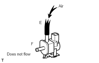
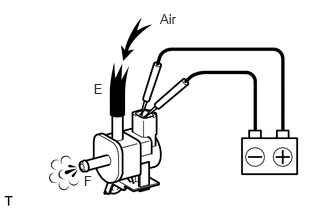
Inspect the No. 1 vacuum switching valve assembly operation.
i.
Check that air does not flow from ports.
ii.
1.666,0.113 1.896,0.269
0.230,0.156
10
Air
0.976,0.843 1.143,0.999
0.167,0.156
10
E
0.874,1.806 1.041,1.962
0.167,0.156
10
F
Apply battery voltage across the terminals.
iii.
Check that air flows from ports.
If operation is not as specified, replace the No. 1 vacuum switching valve assembly.