JF3A TRANSFER / 4WD / AWD 4WD CONTROL SWITCH ON-VEHICLE INSPECTION
PROCEDURE

 84724
1.INSPECT 4WD CONTROL SWITCH
Check the harness and connector (ECU - battery and body ground).
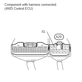
Measure the voltage and resistance according to the value(s) in the table below.
- Standard Voltage:
Tester Connection Condition Specified Condition A29-3 (IG) - Body ground Ignition switch ON 11 to 14 V
If there is a malfunction, inspect the harness or connector. If the harness is malfunctioning, repair or replace harness or connector. If the harness or connector is normal, replace the 4WD control ECU (See page Drivetrain>JF3A TRANSFER / 4WD / AWD>4WD CONTROL ECU>REMOVAL).
- Standard Resistance:
Tester Connection Condition Specified Condition A29-4 (GND) - Body ground Always Below 1 Ω
If there is a malfunction, repair or replace the harness or connector.
Check the harness and connector (switch - ECU).
Disconnect the A28 ECU connector.
Disconnect the J1 switch connector.
Measure the resistance according to the value(s) in the table below.
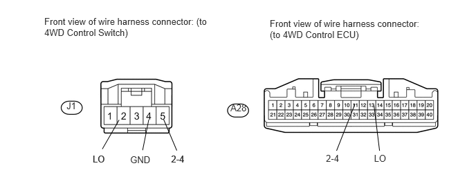
- Standard Resistance:
Tester Connection Condition Specified Condition J1-2 (LO) - A28-13 (LO) Always Below 1 Ω J1-2 (LO) - Body ground Always 10 kΩ or higher J1-4 (GND) - Body ground Always Below 1 Ω J1-5 (2-4) - A28-11 (2-4) Always Below 1 Ω J1-5 (2-4) - Body ground Always 10 kΩ or higher
If the resistance is not as specified, repair or replace the harness or connector.
Check the 4WD control switch.
Turn the ignition switch off.
Connect the J1 switch connector.
Connect the A28 and A29 ECU connectors.
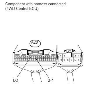
Measure the voltage according to the value(s) in the table below.
- Standard Voltage:
Tester Connection Switch Condition Specified Condition A28-11 (2-4) - Body ground Ignition switch ON
4WD control switch 2WD positionBelow 1.5 V Ignition switch ON
4WD control switch 4H positionBelow 1.5 V Ignition switch ON
4WD control switch 4L position10.5 to 14 V A28-13 (LO) - Body ground Ignition switch ON
4WD control switch 2WD position10.5 to 14 V Ignition switch ON
4WD control switch 4H positionBelow 1.5 V Ignition switch ON
4WD control switch 4L positionBelow 1.5 V
If the voltage is not as specified, check the 4WD control ECU.
Check the 4WD control ECU.
Disconnect the J1 switch connector.
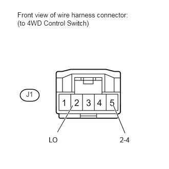
Measure the voltage according to the value(s) in the table below.
- Standard Voltage:
Tester Connection Switch Condition Specified Condition J1-2 (LO) - Body ground Ignition switch ON 10.5 to 14 V J1-5 (2-4) - Body ground Ignition switch ON 10.5 to 14 V
If the voltage is not as specified, replace the 4WD control ECU (See page Drivetrain>JF3A TRANSFER / 4WD / AWD>4WD CONTROL ECU>REMOVAL). If the voltage is normal, replace the 4WD control switch.