DRIVE SHAFT / PROPELLER SHAFT REAR DRIVE SHAFT ASSEMBLY REASSEMBLY
PROCEDURE

 1.INSTALL REAR DRIVE SHAFT DUST SEAL
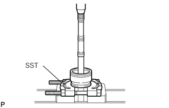
Using SST and a press, press in a new dust seal to the outboard joint shaft assembly.
- SST
- 09950-00020
- NOTICE:
-
Be careful not to damage the dust seal.
41336K
2.INSTALL REAR DRIVE SHAFT DUST COVER
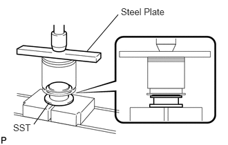
Using SST, a steel plate and press, press in a new dust cover to the inboard joint shaft.
- SST
- 09316-20011
- NOTICE:
-
Be careful not to damage the dust cover.
04438Q
3.INSTALL REAR DRIVE SHAFT OUTBOARD JOINT BOOT
Wrap the spline of the outboard joint shaft with vinyl tape to prevent the boots from being damaged.
Install the new outboard joint boot to the outboard joint shaft.
Pack the outboard joint shaft and boot with grease from the boot kit.
- Standard grease capacity:
234 to 254 g (8.3 to 9.0 oz.)
Install the outboard joint boot into the groove on the outboard joint shaft.
- NOTICE:
-
Keep the groove where you are fitting the boot free of grease.
42346F
4.INSTALL REAR DRIVE SHAFT NO. 2 OUTBOARD JOINT BOOT CLAMP
Install the No. 2 outboard joint boot clamp onto the outboard joint boot.
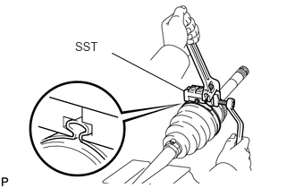
Using SST, pinch the clamp.
- SST
- 09521-24010
- NOTICE:
-
Do not overtighten SST.
42346D
5.INSTALL REAR DRIVE SHAFT OUTBOARD JOINT BOOT CLAMP
Install the outboard joint boot clamp onto the outboard joint boot.
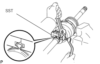
Using SST, pinch the clamp.
- SST
- 09521-24010
- NOTICE:
-
Do not overtighten SST.
6.INSPECT AND ADJUST OUTBOARD JOINT BOOT CLAMP
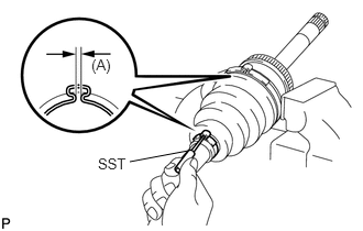
Using SST, inspect and adjust the clearance of the boot clamps.
- SST
- 09240-00020
- Standard Clearance:
Boot setting clamp Clearance Inside 2.8 to 3.8 mm (0.110 to 0.150 in.) Outside 3.0 to 4.0 mm (0.118 to 0.157 in.)
04437D
7.TEMPORARILY INSTALL REAR DRIVE SHAFT INBOARD JOINT BOOT
Wrap the spline of the outboard joint shaft with vinyl tape to prevent the boots from being damaged.
Install the new inboard joint boot to the outboard joint shaft.
8.INSTALL REAR DRIVE SHAFT INBOARD JOINT SHAFT ASSEMBLY
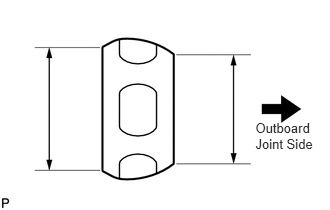
Install the cage to the outboard joint shaft.
- NOTICE:
-
Install the cage with its smaller inner diameter side facing the outboard joint.
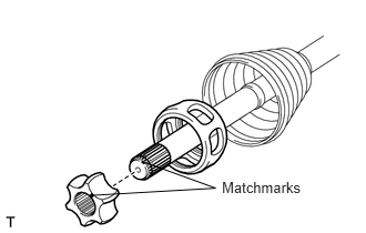
Align the matchmarks and install the inner race onto the outboard joint shaft.
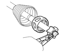
Using a snap ring expander, install a new snap ring.
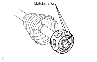
Align the matchmarks placed before removal, and install the cage to the inner race.
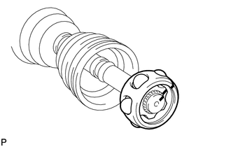
Install the 6 balls.
- HINT:
-
Apply grease onto the balls to keep them from falling out.
Pack the inboard joint shaft and boot with grease from the boot kit.
- Standard grease capacity:
388 to 408 g (13.7 to 14.4 oz.)
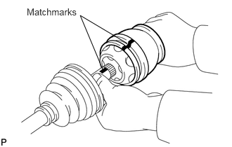
Align the matchmarks placed before removal, and install the inboard joint shaft to the outboard joint shaft.
Install a new snap ring.
04437D
9.INSTALL REAR DRIVE SHAFT INBOARD JOINT BOOT
Install the inboard joint boot into the groove on the outboard joint shaft and inboard joint shaft.
- NOTICE:
-
Keep the groove where you are fitting the boot free of grease.
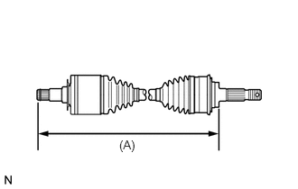
Check whether the drive shaft dimensions are within the following specifications.
- Standard Drive Shaft Length (A):
Drive shaft Length LH 804.5 mm (31.67 in.) RH 842.2 mm (33.16 in.)
42347F
10.INSTALL REAR DRIVE SHAFT NO. 2 INBOARD JOINT BOOT CLAMP
Install the No. 2 inboard joint boot clamp.
- HINT:
-
Use the same procedure as for the outboard side.
42347D
11.INSTALL REAR DRIVE SHAFT INBOARD JOINT BOOT CLAMP
Install the inboard joint boot clamp.
- HINT:
-
Use the same procedure as for the outboard side.
12.INSPECT AND ADJUST INBOARD JOINT BOOT CLAMP
Inspect and adjust the clearance of the boot clamps.
- HINT:
-
Use the same procedure as for the outboard side.
42360M
13.INSTALL REAR DRIVE SHAFT INBOARD JOINT SHAFT SNAP RING
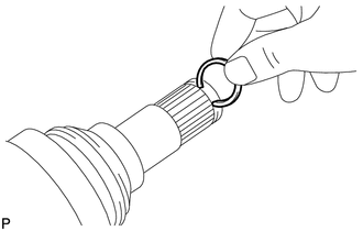
Install a new snap ring onto the inboard joint shaft.
42340B
14.INSPECT REAR DRIVE SHAFT ASSEMBLY
Check whether the drive shaft dimensions are within the following specifications.
- Standard Drive Shaft Length (A):
Drive shaft Length LH 804.5 mm (31.67 in.) RH 842.2 mm (33.16 in.)
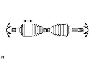
Check for noticeable looseness when turning the joint up and down, left and right, and in the thrust direction.
Check for cracks, damage and grease leakage on the boot joint.
- NOTICE:
-
Keep the drive shaft level while moving it.