SUSPENSION CONTROL SUSPENSION CONTROL SYSTEM PRECAUTION
WHEN LIFTING VEHICLE
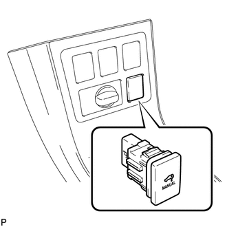
When jacking up or lifting the vehicle , stop operation of the air suspension control system by pressing the height control mode select switch.
DISCONNECTION AND CONNECTION OF HEIGHT CONTROL TUBE (TYPE1)
- NOTICE:
- ·
Disconnection and connection of the height control tube should be performed by hand to prevent foreign objects from entering.
·Never damage the height control tube.
Disconnect the height control tube.
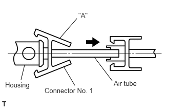
Pinch section "A" of the connector No. 1 and pull it from the housing.
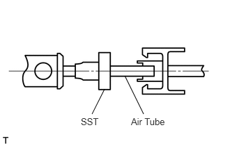
Set the SST to the tube.
- SST
- 09730-00010
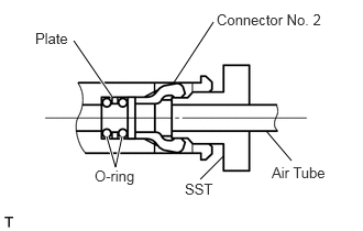
Insert SST into the housing to expand the claw of the connector No. 2 in the housing.
Pull out the tube with SST inserted.
- NOTICE:
-
Do not pull on the tube with excessive force.
Insert a screwdriver into the circular hole on the housing, and remove the connector No. 2, the 2 O-rings and the plate from the housing.
- HINT:
-
The O-rings, plate and connector No. 2 are non-reusable parts.
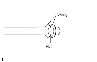
Install 2 O-rings and the plate.
Apply MP grease to 2 new O-rings and the plate and install them to the straight tube or an equivalent.
- NOTICE:
-
Install the plate between the O-rings.
-
Keep foreign matter from adhering to the O-rings and the height control tube in order to prevent air leaks.
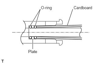
Insert the tube on which the 2 O-rings and plate are installed into the housing, and then push it in lightly with a piece of rolled up cardboard.
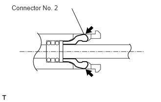
Push the connector No. 2 into the housing to where a clicking sound is heard.
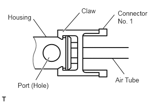
Install the height control tube.
Push the tube and connector No. 1 into the housing to where a clicking sound is heard.
- NOTICE:
- ·
The port (hole) of the housing should be set in the position 90° from the claws of connector No. 1.
·Pull the tube lightly to make sure that it is securely connected.
·Prevent foreign matter from being attached to the O-rings and height control tube. Failure to do so may cause air leakage.
DISCONNECTION AND CONNECTION OF HEIGHT CONTROL TUBE (TYPE2)
- NOTICE:
- ·
Disconnecting and connecting the height control tube should be performed by hand to prevent dust or foreign objects from entering it.
·Be careful not to damage the height control tube.
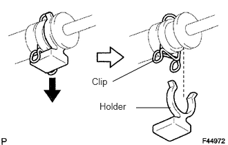
Disconnect the height control tube.
Remove the holder.
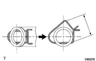
Spread the clip and slowly pull the height control tube straight out.
- NOTICE:
-
Do not completely remove the clip except when replacing it.
Remove the 2 O-rings.
- HINT:
-
Some tubes are equipped with only one O-ring.
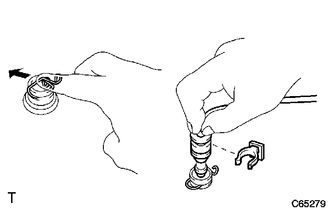
Install the height control tube.
If replacing the clip: Hook one side of the new clip around the union groove, and slide the other side into the opposite side of the union groove.
If not replacing the clip: Install 2 new O-rings to the height control tube and coat them with MP grease No. 2.
- NOTICE:
-
Air leaks may occur if dust or foreign objects come into contact with the O-rings.
- HINT:
-
Some tubes are equipped with only one O-ring.
Securely connect the height control tube straight onto the connector until a clicking sound is heard.
- NOTICE:
-
Connect the height control tube straight in order to prevent air leaks.
Install the height control tube to the holder, being careful not to apply excessive force to the clip.