SUSPENSION CONTROL FRONT ACCELERATION SENSOR INSPECTION
PROCEDURE

 89190A
1.INSPECT ACCELERATION SENSOR ASSEMBLY
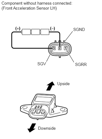
Inspect the acceleration sensor LH.
Connect 3 dry cell batteries of 1.5 V in series.
Connect the positive (+) end of the batteries to terminal 3 (SGV) of the acceleration sensor and the negative (-) end of the batteries to terminal 2 (SGND). Then measure the voltage between terminal 1 (SGRR) and terminal 2 (SGND).
Measure the voltage according to the value(s) in the table below.
- Standard Voltage:
Tester Connection Sensor Condition Specified Condition 1 (SGRR) - 2 (SGND) Sensor stationary Approx. 2.0 to 2.5 V Sensor is tilted Change between approx. 0.9 to 2.3 V
- NOTICE:
-
Do not apply a voltage of more than 6 V.
- HINT:
-
When the acceleration sensor is tilted, it may output a different value.
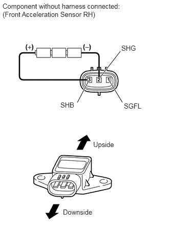
Inspect the acceleration sensor RH.
Connect 3 dry cell batteries of 1.5 V in series.
Connect the positive (+) end of the batteries to terminal 3 (SHB) of the acceleration sensor and the negative (-) end of the batteries to terminal 2 (SHG). Then measure the voltage between terminal 1 (SGFL) and terminal 2 (SHG).
Measure the voltage according to the value(s) in the table below.
- Standard Voltage:
Tester Connection Sensor Condition Specified Condition 1 (SGFL) - 2 (SHG) Sensor stationary Approx. 2.0 to 2.5 V Sensor is tilted Change between approx. 0.9 to 2.3 V
- NOTICE:
-
Do not apply a voltage of more than 6 V.
- HINT:
-
When the acceleration sensor is tilted, it may output a different value.