Home › Suspension › SUSPENSION CONTROL › AIR SUSPENSION SYSTEM
RM27L0U _53 Suspension _049315 SUSPENSION CONTROL _0235712 AIR SUSPENSION SYSTEM C

SUSPENSION CONTROL  AIR SUSPENSION SYSTEM  C1713  Rear Height Control Sensor RH Circuit Malfunction  C1714  Rear Height Control Sensor LH Circuit Malfunction  


DESCRIPTION

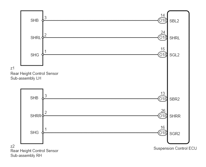
A magnetic circuit installed on the shaft inside the height control sensor rotates around the linear IC. The linear IC outputs voltage corresponding to the level of magnetic strength generated by the magnetic circuit. As a result, voltage corresponding to the shaft rotation angle is supplied to the suspension control ECU.

DTC Code Detection Condition Trouble Area
C1713 With the ignition switch ON, a voltage of 4.7 V or more, or 0.3 V or less at rear height control sensor RH is detected for 1 second.
·

Wire harness or connector

·

Rear height control sensor sub-assembly RH

·

Suspension control ECU


C1714 With the ignition switch ON, a voltage of 4.7 V or more, or 0.3 V or less at rear height control sensor LH is detected for 1 second.
·

Wire harness or connector

·

Rear height control sensor sub-assembly LH

·

Suspension control ECU


WIRING DIAGRAM

C179515E14
0.365,2.292 0.656,2.479 0.292,0.188 10 false z1 0.365,2.479 2.021,3.052 1.656,0.573 10 false Rear Height Control Sensor Sub-assembly LH 1.542,1.708 1.698,1.917 0.156,0.208 10 false 1 0.365,5.021 0.698,5.219 0.333,0.198 10 false z2 0.365,5.177 2.042,5.802 1.677,0.625 10 false Rear Height Control Sensor Sub-assembly RH 5.344,5.094 7.01,5.469 1.667,0.375 10 false Suspension Control ECU 1.542,1.135 1.698,1.344 0.156,0.208 10 false 2 1.542,0.531 1.698,0.74 0.156,0.208 10 false 3 5.583,0.448 5.802,0.656 0.219,0.208 10 false 14 5.594,1.042 5.813,1.25 0.219,0.208 10 false 24 5.896,0.646 6.323,0.854 0.427,0.208 10 false SBL2 5.896,1.24 6.323,1.448 0.427,0.208 10 false SHRL 5.896,1.833 6.323,2.042 0.427,0.208 10 false SGL2 1.063,0.625 1.49,0.833 0.427,0.208 10 false SHB 1.063,1.229 1.49,1.438 0.427,0.208 10 false SHRL 1.063,1.833 1.49,2.042 0.427,0.208 10 false SHG 5.896,3.375 6.323,3.583 0.427,0.208 10 false SBR2 5.896,3.969 6.323,4.177 0.427,0.208 10 false SHRR 5.896,4.583 6.323,4.792 0.427,0.208 10 false SGR2 5.583,1.625 5.802,1.833 0.219,0.208 10 false 15 5.583,3.177 5.802,3.385 0.219,0.208 10 false 13 5.604,3.781 5.823,3.99 0.219,0.208 10 false 26 5.583,4.365 5.802,4.573 0.219,0.208 10 false 16 5.531,0.625 5.833,0.833 0.302,0.208 10 false O18 1.552,4.427 1.708,4.635 0.156,0.208 10 false 1 1.552,3.844 1.708,4.052 0.156,0.208 10 false 2 1.552,3.26 1.708,3.469 0.156,0.208 10 false 3 1.052,3.333 1.479,3.542 0.427,0.208 10 false SHB 1.052,3.958 1.479,4.167 0.427,0.208 10 false SHRR 1.052,4.542 1.479,4.75 0.427,0.208 10 false SHG 5.542,1.219 5.844,1.427 0.302,0.208 10 false O18 5.542,1.823 5.844,2.031 0.302,0.208 10 false O18 5.531,3.365 5.833,3.573 0.302,0.208 10 false O18 5.531,3.958 5.833,4.167 0.302,0.208 10 false O18 5.531,4.552 5.833,4.76 0.302,0.208 10 false O18

CAUTION / NOTICE / HINT

NOTICE:

After replacing the suspension control ECU, perform registration (See page Suspension>SUSPENSION CONTROL>AIR SUSPENSION SYSTEM>REGISTRATION).


PROCEDURE
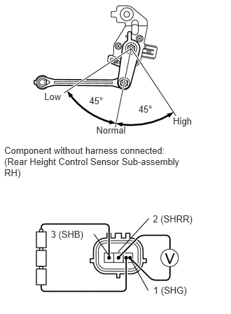
1.INSPECT REAR HEIGHT CONTROL SENSOR SUB-ASSEMBLY
a.
C241587E01
0.659,1.35 0.944,1.526 0.285,0.176 10 Low 2.574,1.723 2.955,1.899 0.382,0.176 10 High 0.064,2.161 2.784,2.686 2.720,0.525 10 Component without harness connected: (Rear Height Control Sensor Sub-assembly RH) 1.432,1.857 1.912,2.032 0.480,0.176 10 Normal 0.756,3.411 1.277,3.587 0.520,0.176 10 3 (SHB) 2.281,4.243 2.841,4.419 0.560,0.176 10 1 (SHG) 2.275,3.176 2.910,3.352 0.635,0.176 10 2 (SHRR) 1.327,1.42 1.591,1.604 0.264,0.183 10 45° 2.059,1.547 2.337,1.718 0.279,0.171 10 45° 2.215,3.254 1.755,3.755 false 1.932,3.842 2.205,4.326 false 1.611,3.791 1.399,3.486 false

Check the rear height control sensor sub-assembly RH: (C1713).

i.

Remove the rear height control sensor sub-assembly RH (See page Suspension>SUSPENSION CONTROL>HEIGHT CONTROL SENSOR>REMOVAL).


ii.

Connect 3 dry cell batteries of 1.5 V in series.


iii.

Connect the positive (+) end of the batteries to terminal 3 (SHB) of the height control sensor and the negative (-) end of the batteries to terminal 1 (SHG). While slowly moving the sensor link up and down, measure the voltage between terminal 2 (SHRR) and terminal 1 (SHG).


iv.

Measure the voltage according to the value(s) in the table below.

Standard Voltage:
Tester Connection Sensor Condition Specified Condition
1 (SHG) - 2 (SHRR) High (45°) 3.60 to 4.52 V
Normal (0°) 2.06 to 2.45 V
Low (-45°) 0.40 to 0.51 V


NOTICE:

Do not apply a voltage of more than 6 V.
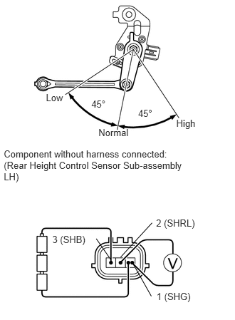


b.
C241587E02
0.055,2.163 2.766,2.698 2.710,0.534 10 Component without harness connected: (Rear Height Control Sensor Sub-assembly LH) 0.672,1.349 0.957,1.525 0.285,0.176 10 Low 2.578,1.717 2.959,1.893 0.382,0.176 10 High 1.44,1.859 1.921,2.035 0.480,0.176 10 Normal 0.765,3.414 1.285,3.590 0.520,0.176 10 3 (SHB) 2.289,4.246 2.850,4.422 0.560,0.176 10 1 (SHG) 2.284,3.179 2.918,3.355 0.635,0.176 10 2 (SHRL) 1.336,1.441 1.601,1.627 0.265,0.186 10 45° 2.02,1.571 2.278,1.736 0.258,0.165 10 45° 2.224,3.257 1.764,3.758 false 1.941,3.845 2.213,4.329 false 1.62,3.794 1.407,3.488 false

Check the rear height control sensor sub-assembly LH: (C1714).

i.

Remove the rear height control sensor sub-assembly LH (See page Suspension>SUSPENSION CONTROL>HEIGHT CONTROL SENSOR>REMOVAL).


ii.

Connect 3 dry cell batteries of 1.5 V in series.


iii.

Connect the positive (+) end of the batteries to terminal 3 (SHB) of the height control sensor and the negative (-) end of the batteries to terminal 1 (SHG). While slowly moving the sensor link up and down, measure the voltage between terminal 2 (SHRL) and terminal 1 (SHG).


iv.

Measure the voltage according to the value(s) in the table below.

Standard Voltage:
Tester Connection Sensor Condition Specified Condition
1 (SHG) - 2 (SHRL) High (45°) 3.60 to 4.52 V
Normal (0°) 2.06 to 2.45 V
Low (-45°) 0.40 to 0.51 V


NOTICE:

Do not apply a voltage of more than 6 V.


Result
Result Proceed to
OK A
NG (Rear height control sensor sub-assembly RH) B
NG (Rear height control sensor sub-assembly LH) C


A

2.CHECK HARNESS AND CONNECTOR (REAR HEIGHT CONTROL SENSOR SUB-ASSEMBLY - SUSPENSION CONTROL ECU)

B

REPLACE REAR HEIGHT CONTROL SENSOR SUB-ASSEMBLY RH

C

REPLACE REAR HEIGHT CONTROL SENSOR SUB-ASSEMBLY LH

2.CHECK HARNESS AND CONNECTOR (REAR HEIGHT CONTROL SENSOR SUB-ASSEMBLY - SUSPENSION CONTROL ECU)
a.

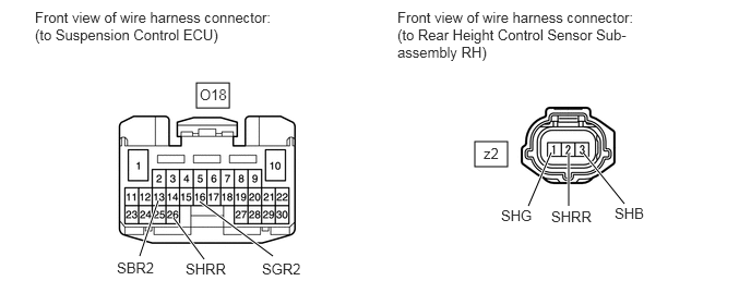
Check the rear height control sensor sub-assembly RH: (C1713).
C353461E01
4.531,1.354 4.844,1.594 0.313,0.24 1.875,0.792 2.188,1.031 0.313,0.24 1.333,2.448 1.51,1.917 true 1.948,2.479 1.656,2.083 true 2.604,2.448 1.906,1.927 true 5.042,1.969 5.26,1.458 true 5.427,1.969 5.427,1.469 true 5.958,1.948 5.573,1.469 true 0.333,0.083 2.708,0.688 2.375,0.604 10 false Front view of wire harness connector: (to Suspension Control ECU) 3.792,0.083 6.167,1.01 2.375,0.927 10 false Front view of wire harness connector: (to Rear Height Control Sensor Sub-assembly RH) 1.906,0.823 2.365,1.021 0.458,0.198 10 false O18 4.615,1.385 4.927,1.583 0.313,0.198 10 false z2 1.115,2.479 1.729,2.677 0.615,0.198 10 false SBR2 1.771,2.49 2.385,2.688 0.615,0.198 10 false SHRR 2.5,2.49 3.115,2.688 0.615,0.198 10 false SGR2 4.781,1.979 5.24,2.177 0.458,0.198 10 false SHG 5.26,1.99 5.875,2.188 0.615,0.198 10 false SHRR 5.865,1.958 6.323,2.156 0.458,0.198 10 false SHB

i.

Disconnect the O18 ECU connector and z2 sensor connector.


ii.

Measure the resistance according to the value(s) in the table below.

Standard Resistance:
Tester Connection Condition Specified Condition
z2-1 (SHG) - O18-16 (SGR2) Always Below 1 Ω
z2-2 (SHRR) - O18-26 (SHRR) Always Below 1 Ω
z2-3 (SHB) - O18-13 (SBR2) Always Below 1 Ω
z2-1 (SHG) or O18-16 (SGR2) - Body ground Always 10 kΩ or higher
z2-2 (SHRR) or O18-26 (SHRR) - Body ground Always 10 kΩ or higher
z2-3 (SHB) or O18-13 (SBR2) - Body ground Always 10 kΩ or higher


b.

Check the rear height control sensor sub-assembly LH: (C1714).
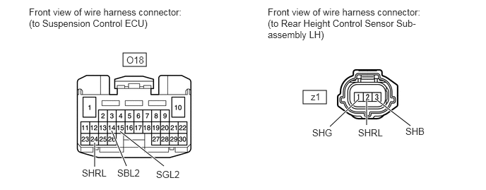
C353461E02
1.813,0.781 2.156,0.979 0.344,0.198 4.469,1.333 4.813,1.531 0.344,0.198 4.865,1.865 5.281,1.469 true 5.406,1.844 5.406,1.469 true 6.052,1.854 5.563,1.479 true 1.396,2.458 1.396,2.104 true 1.865,2.448 1.646,1.927 true 2.417,2.448 1.771,1.938 true 0.427,0.094 2.833,0.771 2.406,0.677 10 false Front view of wire harness connector: (to Suspension Control ECU) 3.948,0.094 6.365,0.969 2.417,0.875 10 false Front view of wire harness connector: (to Rear Height Control Sensor Sub-assembly LH) 1.208,2.469 1.823,2.667 0.615,0.198 10 false SHRL 1.729,2.469 2.344,2.667 0.615,0.198 10 false SBL2 2.302,2.49 2.917,2.688 0.615,0.198 10 false SGL2 4.604,1.875 5.063,2.073 0.458,0.198 10 false SHG 5.281,1.875 5.896,2.073 0.615,0.198 10 false SHRL 5.979,1.854 6.438,2.052 0.458,0.198 10 false SHB 1.865,0.802 2.323,1 0.458,0.198 10 false O18 4.583,1.344 4.896,1.542 0.313,0.198 10 false z1

i.

Disconnect the O18 ECU connector and z1 sensor connector.


ii.

Measure the resistance according to the value(s) in the table below.

Standard Resistance:
Tester Connection Condition Specified Condition
z1-1 (SHG) - O18-15 (SGL2) Always Below 1 Ω
z1-2 (SHRL) - O18-24 (SHRL) Always Below 1 Ω
z1-3 (SHB) - O18-14 (SBL2) Always Below 1 Ω
z1-1 (SHG) or O18-15 (SGL2) - Body ground Always 10 kΩ or higher
z1-2 (SHRL) or O18-24 (SHRL) - Body ground Always 10 kΩ or higher
z1-3 (SHB) or O18-14 (SBL2) - Body ground Always 10 kΩ or higher


OK

REPLACE SUSPENSION CONTROL ECU

NG

REPAIR OR REPLACE HARNESS OR CONNECTOR