Home › Suspension › SUSPENSION CONTROL › AIR SUSPENSION SYSTEM
RM27L0U _53 Suspension _049315 SUSPENSION CONTROL _0235712 AIR SUSPENSION SYSTEM C

SUSPENSION CONTROL  AIR SUSPENSION SYSTEM  C1731  Front Damping Force Control Actuator RH Circuit Malfunction  C1732  Front Damping Force Control Actuator LH Circuit Malfunction  C1733  Rear Damping Force Control Actuator RH Circuit Malfunction  C1734  Rear Damping Force Control Actuator LH Circuit Malfunction  


DESCRIPTION

The absorber control actuator switches the damping force depending on the suspension control ECU signals.

DTC Code Detection Condition Trouble Area
C1731 When either of the following is detected:
·

An actuator open-circuit signal is detected for at least 1 second when the actuator operates.

·

An actuator short-circuit signal is consecutively detected 8 times when the actuator operates.


·

Wire harness or connector

·

Front absorber control actuator RH

·

Suspension control ECU


C1732 When either of the following is detected:
·

An actuator open-circuit signal is detected for at least 1 second when the actuator operates.

·

An actuator short-circuit signal is consecutively detected 8 times when the actuator operates.


·

Wire harness or connector

·

Front absorber control actuator LH

·

Suspension control ECU


C1733 When either of the following is detected:
·

An actuator open-circuit signal is detected for at least 1 second when the actuator operates.

·

An actuator short-circuit signal is consecutively detected 8 times when the actuator operates.


·

Wire harness or connector

·

Rear absorber control actuator RH

·

Suspension control ECU


C1734 When either of the following is detected:
·

An actuator open-circuit signal is detected for at least 1 second when the actuator operates.

·

An actuator short-circuit signal is consecutively detected 8 times when the actuator operates.


·

Wire harness or connector

·

Rear absorber control actuator LH

·

Suspension control ECU


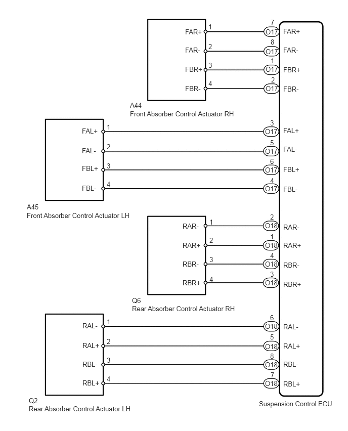
WIRING DIAGRAM

C179519E04
2.677,2.26 4.938,2.594 2.26,0.333 10 false Front Absorber Control Actuator RH 2.677,2.083 3.073,2.271 0.396,0.188 10 false A44 0.552,4.354 2.792,4.552 2.24,0.198 10 false Front Absorber Control Actuator LH 0.552,4.177 0.948,4.365 0.396,0.188 10 false A45 2.719,6.271 4.979,6.583 2.26,0.313 10 false Rear Absorber Control Actuator RH 2.719,6.104 3.115,6.292 0.396,0.188 10 false Q6 0.594,8.333 2.833,8.625 2.24,0.292 10 false Rear Absorber Control Actuator LH 0.594,8.167 0.99,8.354 0.396,0.188 10 false Q2 5.333,8.229 7,8.604 1.667,0.375 10 false Suspension Control ECU 3.813,1.344 4.208,1.552 0.396,0.208 10 false FBR+ 3.813,1.74 4.208,1.948 0.396,0.208 10 false FBR- 3.813,0.573 4.208,0.781 0.396,0.208 10 false FAR+ 3.813,0.948 4.208,1.156 0.396,0.208 10 false FAR- 5.833,1.354 6.229,1.563 0.396,0.208 10 false FBR+ 5.833,1.75 6.229,1.958 0.396,0.208 10 false FBR- 5.833,0.563 6.229,0.771 0.396,0.208 10 false FAR+ 5.833,0.948 6.229,1.156 0.396,0.208 10 false FAR- 2.198,7.719 2.354,7.927 0.156,0.208 10 false 4 2.198,7.333 2.354,7.542 0.156,0.208 10 false 3 2.198,6.948 2.354,7.156 0.156,0.208 10 false 2 2.198,6.542 2.354,6.75 0.156,0.208 10 false 1 4.313,5.667 4.469,5.875 0.156,0.208 10 false 4 4.313,5.26 4.469,5.469 0.156,0.208 10 false 3 4.313,4.865 4.469,5.073 0.156,0.208 10 false 2 4.313,4.49 4.469,4.698 0.156,0.208 10 false 1 5.573,7.635 5.698,7.813 0.125,0.177 10 false 7 5.563,7.25 5.698,7.417 0.135,0.167 10 false 8 5.563,6.854 5.688,7.021 0.125,0.167 10 false 5 5.563,6.458 5.698,6.625 0.135,0.167 10 false 6 5.563,5.563 5.698,5.729 0.135,0.167 10 false 3 5.563,5.177 5.677,5.333 0.115,0.156 10 false 4 5.563,4.792 5.677,4.958 0.115,0.167 10 false 1 5.563,4.385 5.698,4.563 0.135,0.177 10 false 2 5.563,3.24 5.698,3.427 0.135,0.188 10 false 6 5.563,3.635 5.781,3.844 0.219,0.208 10 false 4 5.563,2.448 5.688,2.604 0.125,0.156 10 false 3 5.563,2.854 5.708,3.021 0.146,0.167 10 false 5 5.573,1.167 5.688,1.354 0.115,0.188 10 false 1 5.583,1.563 5.708,1.729 0.125,0.167 10 false 2 5.573,0.375 5.677,0.531 0.104,0.156 10 false 7 5.573,0.781 5.698,0.958 0.125,0.177 10 false 8 5.469,0.979 5.76,1.188 0.292,0.208 10 false O17 2.198,3.708 2.354,3.917 0.156,0.208 10 false 4 2.198,3.333 2.354,3.542 0.156,0.208 10 false 3 2.198,2.938 2.354,3.146 0.156,0.208 10 false 2 2.198,2.531 2.354,2.74 0.156,0.208 10 false 1 4.292,1.635 4.448,1.844 0.156,0.208 10 false 4 4.292,1.26 4.448,1.469 0.156,0.208 10 false 3 4.292,0.875 4.448,1.083 0.156,0.208 10 false 2 4.292,0.469 4.448,0.677 0.156,0.208 10 false 1 1.688,3.385 2.083,3.594 0.396,0.208 10 false FBL+ 1.688,3.792 2.083,4 0.396,0.208 10 false FBL- 1.688,2.615 2.083,2.823 0.396,0.208 10 false FAL+ 1.688,3.021 2.083,3.229 0.396,0.208 10 false FAL- 5.833,3.406 6.229,3.615 0.396,0.208 10 false FBL+ 5.833,3.813 6.229,4.021 0.396,0.208 10 false FBL- 5.833,2.604 6.229,2.813 0.396,0.208 10 false FAL+ 5.833,2.99 6.229,3.198 0.396,0.208 10 false FAL- 3.76,5.74 4.198,5.948 0.438,0.208 10 false RBR+ 3.76,5.354 4.198,5.563 0.438,0.208 10 false RBR- 3.76,4.969 4.198,5.177 0.438,0.208 10 false RAR+ 3.76,4.573 4.198,4.781 0.438,0.208 10 false RAR- 5.833,5.771 6.271,5.979 0.438,0.208 10 false RBR+ 5.833,5.375 6.271,5.583 0.438,0.208 10 false RBR- 5.833,4.969 6.271,5.177 0.438,0.208 10 false RAR+ 5.833,4.594 6.271,4.802 0.438,0.208 10 false RAR- 1.698,7.802 2.135,8.01 0.438,0.208 10 false RBL+ 1.698,7.417 2.135,7.625 0.438,0.208 10 false RBL- 1.698,7.031 2.135,7.24 0.438,0.208 10 false RAL+ 1.698,6.625 2.135,6.833 0.438,0.208 10 false RAL- 5.833,7.823 6.271,8.031 0.438,0.208 10 false RBL+ 5.833,7.417 6.271,7.625 0.438,0.208 10 false RBL- 5.833,7.042 6.271,7.25 0.438,0.208 10 false RAL+ 5.833,6.646 6.271,6.854 0.438,0.208 10 false RAL- 5.469,0.573 5.76,0.781 0.292,0.208 10 false O17 5.469,1.74 5.76,1.948 0.292,0.208 10 false O17 5.469,1.344 5.76,1.552 0.292,0.208 10 false O17 5.458,3.031 5.75,3.24 0.292,0.208 10 false O17 5.458,2.625 5.75,2.833 0.292,0.208 10 false O17 5.458,3.802 5.75,4.01 0.292,0.208 10 false O17 5.458,3.417 5.75,3.625 0.292,0.208 10 false O17 5.458,4.563 5.75,4.771 0.292,0.208 10 false O18 5.458,4.969 5.75,5.177 0.292,0.208 10 false O18 5.458,5.354 5.75,5.563 0.292,0.208 10 false O18 5.458,5.74 5.75,5.948 0.292,0.208 10 false O18 5.458,6.635 5.75,6.844 0.292,0.208 10 false O18 5.458,7.052 5.75,7.26 0.292,0.208 10 false O18 5.458,7.427 5.75,7.635 0.292,0.208 10 false O18 5.458,7.813 5.75,8.021 0.292,0.208 10 false O18

CAUTION / NOTICE / HINT

NOTICE:

After replacing the suspension control ECU, perform registration (See page Suspension>SUSPENSION CONTROL>AIR SUSPENSION SYSTEM>REGISTRATION).


PROCEDURE

1.PERFORM ACTIVE TEST USING TECHSTREAM (REAR GATE SOLENOID)
a.

Turn the ignition switch off.


b.

Connect the Techstream to the DLC3.


c.

Turn the ignition switch to ON, and turn the Techstream main switch on.


d.

Enter the following menus: Chassis / Air suspension / Active Test.

Air Suspension
Tester Display Test Part Control Range Diagnostic Note
Damper Step FR Damper step (Front RH) /
min.: 0 step
max.: 255 steps
min.: 1 step
max.: 16 steps
-
Damper Step FL Damper step (Front LH) /
min.: 0 step
max.: 255 steps
min.: 1 step
max.: 16 steps
-
Damper Step RR Damper step (Rear RH) /
min.: 0 step
max.: 255 steps
min.: 1 step
max.: 16 steps
-
Damper Step RL Damper step (Rear LH) /
min.: 0 step
max.: 255 steps
min.: 1 step
max.: 16 steps
-

OK:

The absorber control actuator operates.


OK

NG

2.INSPECT ABSORBER CONTROL ACTUATOR
a.

Turn the ignition switch off.


b.
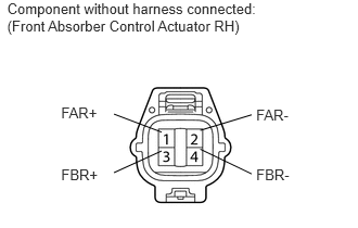
C179520E01
0.069,0 2.628,0.351 2.560,0.351 10 Component without harness connected: (Front Absorber Control Actuator RH) 0.587,1.594 1.035,1.778 0.448,0.184 10 FBR+ 2.46,1.589 2.977,1.773 0.517,0.184 10 FBR- 1.923,1.431 2.416,1.668 false 1.551,1.448 1.094,1.656 false 0.587,0.998 1.035,1.182 0.448,0.184 10 FAR+ 2.46,1.022 2.977,1.205 0.517,0.184 10 FAR- 1.923,1.25 2.416,1.101 false 1.551,1.267 1.094,1.094 false

Check the front absorber control actuator RH: (C1731).

i.

Disconnect the A44 actuator connector.


ii.

Measure the resistance according to the value(s) in the table below.

Standard Resistance:
Tester Connection Sensor Condition Specified Condition
1 (FAR+) - 2 (FAR-) Always 6.4 to 7.2 Ω
3 (FBR+) - 4 (FBR-) Always 6.4 to 7.2 Ω


c.
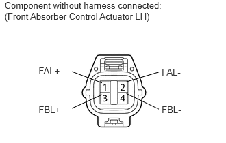
C179520E02
0.069,0 2.628,0.351 2.560,0.351 10 Component without harness connected: (Front Absorber Control Actuator LH) 0.587,1.594 1.035,1.778 0.448,0.184 10 FBL+ 2.46,1.589 2.977,1.773 0.517,0.184 10 FBL- 1.923,1.431 2.416,1.668 false 1.551,1.448 1.094,1.656 false 0.587,0.998 1.035,1.182 0.448,0.184 10 FAL+ 2.46,1.022 2.977,1.205 0.517,0.184 10 FAL- 1.923,1.25 2.416,1.101 false 1.551,1.267 1.094,1.094 false

Check the front absorber control actuator LH: (C1732).

i.

Disconnect the A45 actuator connector.


ii.

Measure the resistance according to the value(s) in the table below.

Standard Resistance:
Tester Connection Sensor Condition Specified Condition
1 (FAL+) - 2 (FAL-) Always 6.4 to 7.2 Ω
3 (FBL+) - 4 (FBL-) Always 6.4 to 7.2 Ω


d.
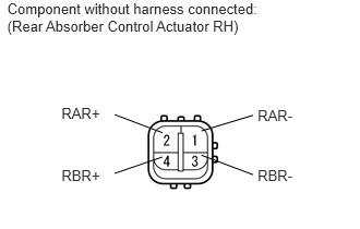
C179521E01
0.069,0 2.628,0.351 2.560,0.351 10 Component without harness connected: (Rear Absorber Control Actuator RH) 0.587,1.594 1.035,1.778 0.448,0.184 10 RBR+ 2.46,1.589 2.977,1.773 0.517,0.184 10 RBR- 1.923,1.482 2.416,1.668 false 1.551,1.499 1.094,1.656 false 0.587,0.998 1.035,1.182 0.448,0.184 10 RAR+ 2.46,1.022 2.977,1.205 0.517,0.184 10 RAR- 1.923,1.25 2.416,1.101 false 1.551,1.267 1.094,1.094 false

Check the rear absorber control actuator RH: (C1733).

i.

Disconnect the Q6 actuator connector.


ii.

Measure the resistance according to the value(s) in the table below.

Standard Resistance:
Tester Connection Sensor Condition Specified Condition
1 (RAR-) - 2 (RAR+) Always 6.4 to 7.2 Ω
3 (RBR-) - 4 (RBR+) Always 6.4 to 7.2 Ω


e.
C179521E02
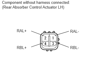
0.069,0 2.628,0.351 2.560,0.351 10 Component without harness connected: (Rear Absorber Control Actuator LH) 0.587,1.594 1.035,1.778 0.448,0.184 10 RBL+ 2.46,1.589 2.977,1.773 0.517,0.184 10 RBL- 1.923,1.482 2.416,1.668 false 1.551,1.499 1.094,1.656 false 0.587,0.998 1.035,1.182 0.448,0.184 10 RAL+ 2.46,1.022 2.977,1.205 0.517,0.184 10 RAL- 1.923,1.25 2.416,1.101 false 1.551,1.267 1.094,1.094 false

Check the rear absorber control actuator LH: (C1734).

i.

Disconnect the Q2 actuator connector.


ii.

Measure the resistance according to the value(s) in the table below.

Standard Resistance:
Tester Connection Sensor Condition Specified Condition
1 (RAL-) - 2 (RAL+) Always 6.4 to 7.2 Ω
3 (RBL-) - 4 (RBL+) Always 6.4 to 7.2 Ω


Result
Result Proceed to
OK A
NG (Front absorber control actuator RH) B
NG (Front absorber control actuator LH) C
NG (Rear absorber control actuator RH) D
NG (Rear absorber control actuator LH) E


A

3.CHECK HARNESS AND CONNECTOR (ABSORBER CONTROL ACTUATOR - ECU AND BODY GROUND)

B

REPLACE FRONT ABSORBER CONTROL ACTUATOR RH

C

REPLACE FRONT ABSORBER CONTROL ACTUATOR LH

D

REPLACE REAR SHOCK ABSORBER ASSEMBLY RH

E

REPLACE REAR SHOCK ABSORBER ASSEMBLY LH

3.CHECK HARNESS AND CONNECTOR (ABSORBER CONTROL ACTUATOR - ECU AND BODY GROUND)
a.

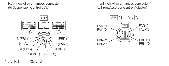
Check the front side absorber control actuator.
C353462E01
1.698,0.667 2.021,0.865 0.323,0.198 4.667,0.656 4.99,0.854 0.323,0.198 5.375,0.646 5.698,0.844 0.323,0.198 4.615,1.177 5.135,1.365 true 4.615,1.771 5.167,1.521 true 5.427,1.375 5.844,1.146 true 5.438,1.521 5.833,1.719 true 1.281,1.625 1.667,1.573 true 1.365,1.802 1.75,1.583 true 1.354,1.979 1.833,1.625 true 1.521,2.208 1.875,1.625 true 2.01,2.177 1.958,1.573 true 2.292,1.625 2.052,1.563 true 2.198,2.031 2.01,1.677 true 2.271,1.833 2.073,1.667 true 0.344,0.063 2.698,0.656 2.354,0.594 10 false Rear view of wire harness connector: (to Suspension Control ECU) 4.094,0.063 6.49,0.708 2.396,0.646 10 false Front view of wire harness connector: (to Front Absorber Control Actuator) 1.74,0.688 2.198,0.885 0.458,0.198 10 false O17 5.052,0.656 5.365,0.854 0.313,0.198 10 false *1 5.417,0.656 5.875,0.854 0.458,0.198 10 false A45 5.74,0.656 6.052,0.854 0.313,0.198 10 false *2 4.115,1.01 4.656,1.365 0.542,0.354 10 false FAR-*1 FAL-*2 5.885,1 6.448,1.365 0.563,0.365 10 false FAR+*1 FAL+*2 5.896,1.604 6.49,1.979 0.594,0.375 10 false FBR+*1 FBL+*2 4.115,1.625 4.688,1.969 0.573,0.344 10 false FBR-*1 FBL-*2 0.719,1.552 1.948,1.75 1.229,0.198 10 false 6 (FBL+) 0.802,1.76 2.031,1.958 1.229,0.198 10 false 5 (FAL-) 0.854,2 2.083,2.198 1.229,0.198 10 false 4 (FBL-) 1.167,2.208 2.396,2.406 1.229,0.198 10 false 3 (FAL+) 1.854,2.208 3.083,2.406 1.229,0.198 10 false 2 (FBR-) 2.229,1.99 3.458,2.188 1.229,0.198 10 false 8 (FAR-) 2.344,1.781 3.573,1.979 1.229,0.198 10 false 7 (FAR+) 2.344,1.552 3.573,1.75 1.229,0.198 10 false 1 (FBR+) 4.708,0.667 5.167,0.865 0.458,0.198 10 false A44 0.208,2.521 1.74,2.719 1.531,0.198 10 false *1: for RH 1.271,2.521 2.802,2.719 1.531,0.198 10 false *2: for LH

i.

Connect the A44 or A45 front absorber control actuator connector.


ii.

Disconnect the O17 ECU connector.


iii.

Measure the resistance according to the value(s) in the table below.

Standard Resistance:
for Front RH: (C1731)
Tester Connection Condition Specified Condition
A44-1 (FAR+) - O17-7 (FAR+) Always Below 1 Ω
A44-2 (FAR-) - O17-8 (FAR-) Always Below 1 Ω
A44-3 (FBR+) - O17-1 (FBR+) Always Below 1 Ω
A44-4 (FBR-) - O17-2 (FBR-) Always Below 1 Ω
A44-1 (FAR+) or O17-7 (FAR+) - Body ground Always 10 kΩ or higher
A44-2 (FAR-) or O17-8 (FAR-) - Body ground Always 10 kΩ or higher
A44-3 (FBR+) or O17-1 (FBR+) - Body ground Always 10 kΩ or higher
A44-4 (FBR-) or O17-2 (FBR-) - Body ground Always 10 kΩ or higher

for Front LH: (C1732)
Tester Connection Condition Specified Condition
A45-1 (FAL+) - O17-3 (FAL+) Always Below 1 Ω
A45-2 (FAL-) - O17-5 (FAL-) Always Below 1 Ω
A45-3 (FBL+) - O17-6 (FBL+) Always Below 1 Ω
A45-4 (FBL-) - O17-4 (FBL-) Always Below 1 Ω
A45-1 (FAL+) or O17-3 (FAL+) - Body ground Always 10 kΩ or higher
A45-2 (FAL-) or O17-5 (FAL-) - Body ground Always 10 kΩ or higher
A45-3 (FBL+) or O17-6 (FBL+) - Body ground Always 10 kΩ or higher
A45-4 (FBL-) or O17-4 (FBL-) - Body ground Always 10 kΩ or higher


b.

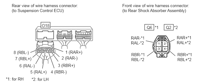
Check the rear side absorber control actuator.
C353463E01
1.375,0.75 1.688,0.948 0.313,0.198 5.521,0.823 5.833,1.021 0.313,0.198 4.865,0.823 5.177,1.021 0.313,0.198 4.948,1.896 5.292,1.646 true 4.906,1.375 5.292,1.458 true 5.604,1.458 5.875,1.333 true 5.604,1.635 5.896,1.885 true 1.75,1.604 2.125,1.74 true 1.667,1.615 2,1.917 true 1.625,1.615 1.958,2.073 true 1.583,1.625 1.823,2.302 true 1.542,1.615 1.427,2.313 true 1.5,1.625 1.198,2.156 true 1.458,1.625 1.094,1.938 true 1.417,1.615 1.021,1.771 true 0.396,0.104 2.771,0.719 2.375,0.615 10 false Rear view of wire harness connector: (to Suspension Control ECU) 4.115,0.104 6.521,0.74 2.406,0.635 10 false Front view of wire harness connector: (to Rear Shock Absorber Assembly) 1.406,0.781 1.865,0.979 0.458,0.198 10 false O18 0.458,1.688 1.688,1.885 1.229,0.198 10 false 8 (RBL-) 0.51,1.896 1.74,2.094 1.229,0.198 10 false 7 (RBL+) 0.656,2.135 1.885,2.333 1.229,0.198 10 false 6 (RAL-) 1.021,2.344 2.25,2.542 1.229,0.198 10 false 5 (RAL+) 2.198,1.677 3.427,1.875 1.229,0.198 10 false 1 (RAR+) 2.073,1.875 3.302,2.073 1.229,0.198 10 false 2 (RAR-) 1.948,2.125 3.177,2.323 1.229,0.198 10 false 3 (RBR+) 1.708,2.344 2.938,2.542 1.229,0.198 10 false 4 (RBR-) 4.938,0.844 5.25,1.042 0.313,0.198 10 false Q6 5.208,0.844 5.521,1.042 0.313,0.198 10 false *1 5.583,0.844 5.896,1.042 0.313,0.198 10 false Q2 5.854,0.844 6.167,1.042 0.313,0.198 10 false *2 4.406,1.198 5,1.552 0.594,0.354 10 false RAR-*1 RAL-*2 5.948,1.188 6.583,1.531 0.635,0.344 10 false RAR+*1 RAL+*2 4.417,1.76 4.99,2.135 0.573,0.375 10 false RBR-*1 RBL-*2 5.969,1.76 6.563,2.135 0.594,0.375 10 false RBR+*1 RBL+*2 0.198,2.583 1.729,2.781 1.531,0.198 10 false *1: for RH 1.063,2.594 2.594,2.792 1.531,0.198 10 false *2: for LH

i.

Connect the Q2 or Q6 rear absorber control actuator connector.


ii.

Disconnect the O18 ECU connector.


iii.

Measure the resistance according to the value(s) in the table below.

Standard Resistance:
for Rear RH: (C1733)
Tester Connection Condition Specified Condition
Q6-1 (RAR-) - O18-2 (RAR-) Always Below 1 Ω
Q6-2 (RAR+) - O18-1 (RAR+) Always Below 1 Ω
Q6-3 (RBR-) - O18-4 (RBR-) Always Below 1 Ω
Q6-4 (RBR+) - O18-3 (RBR+) Always Below 1 Ω
Q6-1 (RAR-) or O18-2 (RAR-) - Body ground Always 10 kΩ or higher
Q6-2 (RAR+) or O18-1 (RAR+) - Body ground Always 10 kΩ or higher
Q6-3 (RBR-) or O18-4 (RBR-) - Body ground Always 10 kΩ or higher
Q6-4 (RBR+) or O18-3 (RBR+) - Body ground Always 10 kΩ or higher

for Rear LH: (C1734)
Tester Connection Condition Specified Condition
Q2-1 (RAL-) - O18-6 (RAL-) Always Below 1 Ω
Q2-2 (RAL+) - O18-5 (RAL+) Always Below 1 Ω
Q2-3 (RBL-) - O18-8 (RBL-) Always Below 1 Ω
Q2-4 (RBL+) - O18-7 (RBL+) Always Below 1 Ω
Q2-1 (RAL-) or O18-6 (RAL-) - Body ground Always 10 kΩ or higher
Q2-2 (RAL+) or O18-5 (RAL+) - Body ground Always 10 kΩ or higher
Q2-3 (RBL-) or O18-8 (RBL-) - Body ground Always 10 kΩ or higher
Q2-4 (RBL+) or O18-7 (RBL+) - Body ground Always 10 kΩ or higher


OK

REPLACE SUSPENSION CONTROL ECU

NG

REPAIR OR REPLACE HARNESS OR CONNECTOR