Home › Suspension › SUSPENSION CONTROL › AIR SUSPENSION SYSTEM
RM27L0U _53 Suspension _049315 SUSPENSION CONTROL _0235712 AIR SUSPENSION SYSTEM C

SUSPENSION CONTROL  AIR SUSPENSION SYSTEM  C1791  Absorber Control Switch Circuit (Test Mode DTC)  


DESCRIPTION

The absorber control switch is used to select the damping force mode of the shock absorber.

DTC Code Detection Condition Trouble Area
C1791 Absorber control switch signal does not change.
·

Absorber control switch (Suspension control switch)

·

Wire harness or connector

·

Suspension control ECU


HINT:

This DTC is output only when the sensor signal check is done.


WIRING DIAGRAM
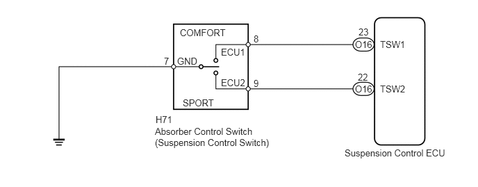
C179524E04
5.167,2.208 6.771,2.396 1.604,0.188 10 false Suspension Control ECU 2.333,1.708 2.646,1.896 0.313,0.188 10 false H71 3.802,1.167 3.938,1.354 0.135,0.188 10 false 9 3.802,0.5 3.938,0.688 0.135,0.188 10 false 8 5.365,1.073 5.542,1.229 0.177,0.156 10 false 22 5.323,0.583 5.615,0.771 0.292,0.188 10 false O16 5.375,0.396 5.563,0.563 0.188,0.167 10 false 23 5.698,1.25 6.177,1.438 0.479,0.188 10 false TSW2 5.698,0.583 6.177,0.771 0.479,0.188 10 false TSW1 3.313,0.698 3.74,0.885 0.427,0.188 10 false ECU1 3.313,1.156 3.74,1.344 0.427,0.188 10 false ECU2 2.656,0.833 3.01,1.021 0.354,0.188 10 false GND 2.698,0.406 3.448,0.594 0.75,0.188 10 false COMFORT 2.74,1.458 3.281,1.646 0.542,0.188 10 false SPORT 2.458,0.833 2.594,1.021 0.135,0.188 10 false 7 2.323,1.885 4.177,2.542 1.854,0.656 10 false Absorber Control Switch (Suspension Control Switch) 5.323,1.25 5.615,1.438 0.292,0.188 10 false O16

CAUTION / NOTICE / HINT

NOTICE:

After replacing the suspension control ECU, perform registration (See page Suspension>SUSPENSION CONTROL>AIR SUSPENSION SYSTEM>REGISTRATION).


PROCEDURE

1.READ VALUE USING TECHSTREAM (ABSORBER CONTROL SWITCH)
a.

Turn the ignition switch off.


b.

Connect the Techstream to the DLC3.


c.

Turn the ignition switch to ON, and turn the Techstream main switch on.


d.

Enter the following menus: Chassis / Air suspension / Data List.

Air Suspension
Tester Display Measurement Item/Range Normal Condition Diagnostic Note
Damping Control Switch Absorber control switch /
NORMAL, COMFORT or SPORT
Indicates current absorber control switch position -


e.

Check that the value displayed on the Techstream changes by operating the absorber control switch "COMFORT" or "SPORT".

OK:

Absorber control switch value changes.


Result
Result Proceed to
NG A
OK (When troubleshooting according to the Problem Symptoms Table) B
OK (When troubleshooting according to the DTC Chart) C


A

2.INSPECT ABSORBER CONTROL SWITCH

B

PROCEED TO NEXT CIRCUIT INSPECTION SHOWN IN PROBLEM SYMPTOMS TABLE

C

2.INSPECT ABSORBER CONTROL SWITCH
a.
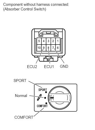
C179525E03
1.75,1.729 1.802,2.281 true 1.573,1.74 1.302,2.281 true 1.958,1.74 2.323,2.271 true 1.031,2.917 1.521,3.156 true 1.219,4.188 1.583,3.885 true 1.063,3.438 1.573,3.51 true 0.521,4.135 1.25,4.313 0.729,0.177 10 false COMFORT 0.49,2.813 1,2.99 0.51,0.177 10 false SPORT 0.979,2.313 1.396,2.49 0.417,0.177 10 false ECU2 1.594,2.313 2.01,2.49 0.417,0.177 10 false ECU1 2.167,2.302 2.563,2.479 0.396,0.177 10 false GND 0.115,0.073 2.646,0.594 2.531,0.521 10 false Component without harness connected: (Absorber Control Switch) 0.542,3.354 1.031,3.531 0.49,0.177 10 false Normal

Turn the ignition switch off.


b.

Remove the absorber control switch.


c.

Measure the resistance according to the value(s) in the table below.

Standard Resistance:
Tester Connection Switch Condition Specified Condition
7 (GND) - 8 (ECU1) COMFORT position Below 1 Ω
Normal position 10 kΩ or higher
7 (GND) - 9 (ECU2) SPORT position Below 1 Ω
Normal position 10 kΩ or higher


OK

3.CHECK HARNESS AND CONNECTOR (ABSORBER CONTROL SWITCH - ECU AND BODY GROUND)

NG

REPLACE SUSPENSION CONTROL SWITCH

3.CHECK HARNESS AND CONNECTOR (ABSORBER CONTROL SWITCH - ECU AND BODY GROUND)
a.

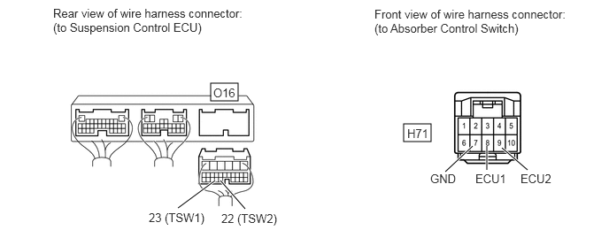
Disconnect the O16 ECU connector.

C353468E01
2.479,0.979 2.802,1.188 0.323,0.208 4.75,1.458 5.073,1.667 0.323,0.208 5.24,2.021 5.563,1.719 true 5.729,2 5.729,1.719 true 6.208,2 5.906,1.74 true 2.094,2.448 2.531,2.125 true 2.885,2.458 2.594,2.125 true 0.625,0.073 2.979,0.74 2.354,0.667 10 false Rear view of wire harness connector: (to Suspension Control ECU) 4.406,0.083 6.76,0.75 2.354,0.667 10 false Front view of wire harness connector: (to Absorber Control Switch) 2.51,1.01 2.969,1.208 0.458,0.198 10 false O16 1.75,2.479 3.125,2.677 1.375,0.198 10 false 23 (TSW1) 2.604,2.49 3.979,2.688 1.375,0.198 10 false 22 (TSW2) 4.792,1.49 5.25,1.688 0.458,0.198 10 false H71 5.063,2.021 5.521,2.219 0.458,0.198 10 false GND 5.594,2.021 6.208,2.219 0.615,0.198 10 false ECU1 6.125,2.021 6.74,2.219 0.615,0.198 10 false ECU2


b.

Measure the resistance according to the value(s) in the table below.

Standard Resistance:
Tester Connection Condition Specified Condition
H71-8 (ECU1) - O16-23 (TSW1) Always Below 1 Ω
H71-9 (ECU2) - O16-22 (TSW2) Always Below 1 Ω
H71-7 (GND) - Body ground Always Below 1 Ω
H71-8 (ECU1) or O16-23 (TSW1) - Body ground Always 10 kΩ or higher
H71-9 (ECU2) or O16-22 (TSW2) - Body ground Always 10 kΩ or higher


OK

REPLACE SUSPENSION CONTROL ECU

NG

REPAIR OR REPLACE HARNESS OR CONNECTOR