Home › Suspension › FRONT SUSPENSION › FRONT SHOCK ABSORBER
RM27L0U _53 Suspension _049317 FRONT SUSPENSION _0235716 FRONT SHOCK ABSORBER A

FRONT SUSPENSION  FRONT SHOCK ABSORBER  REASSEMBLY  


PROCEDURE

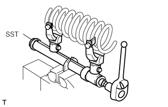
Hide 48132 1.INSTALL FRONT COIL SPRING

C159782E01
0.115,0.613 0.414,0.758 0.299,0.144 10 SST 0.472,0.693 0.648,0.812 false

a.

Secure SST in a vise.

SST
09727-30022  


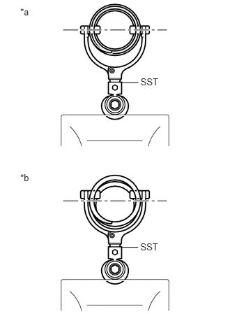
b.
C275706E04
0.303,0.093 0.473,0.253 0.170,0.161 10 *a 0.303,2.563 0.473,2.723 0.170,0.160 10 *b 2.101,1.14 2.417,1.303 0.317,0.163 10 SST 1.823,1.23 2.067,1.23 false 2.098,3.593 2.414,3.756 0.317,0.163 10 SST 1.82,3.683 2.064,3.683 false

Attach the arm of SST to the diameter of the coil spring.

Text in Illustration
*a Correct
*b Incorrect

CAUTION:
·

Make sure that the coil spring is installed so that the distance between the upper and lower hooks of SST is at the maximum.

·

Make sure that the claws of the hooks are securely attached.


c.

Using SST, compress the coil spring.

CAUTION:
·

If the coil spring bends during the compression, immediately stop the compression and reinstall SST.

·

Do not compress the spring until the coil springs contact each other.

·

Do not use an impact wrench.


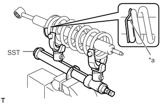
d.
C155966E06
0.708,1.083 0.479,1.083 false 2.719,0.427 3.156,1.156 true 3.115,1.177 3.313,1.365 0.198,0.188 10 false *a 0.156,1.021 0.469,1.177 0.313,0.156 10 false SST

Install the coil spring to the shock absorber.

Text in Illustration
*a Lower End

HINT:

Fit the lower end of the coil spring into the recess of the spring seat of the shock absorber.


Hide 48609 2.INSTALL FRONT SUSPENSION SUPPORT SUB-ASSEMBLY (w/o Air Suspension)

a.

Install the 2 cushions, 2 retainers and suspension support to the piston rod.


b.

Temporarily install a new suspension support to front shock absorber nut.


c.

Position the suspension support as shown in the illustration.
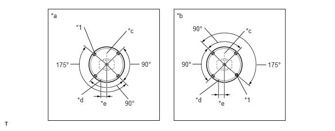
C155967E02
2.671,2.13 2.919,2.277 0.248,0.147 10 90° 2.984,1.372 2.785,1.372 false 1.702,1.372 1.503,1.372 false 1.09,0.255 1.302,0.433 0.212,0.178 10 *a 2.735,0.569 2.947,0.764 0.211,0.195 10 *c 2.029,1.147 1.8,0.581 false 5.259,0.569 5.470,0.764 0.211,0.195 10 *c 4.182,2.05 4.374,2.219 0.192,0.169 10 *d 1.656,2.05 1.848,2.219 0.192,0.169 10 *d 4.674,2.127 4.909,2.302 0.235,0.174 10 *e 2.152,2.127 2.387,2.302 0.235,0.174 10 *e 5.726,1.301 6.067,1.448 0.341,0.147 10 175° 1.194,1.301 1.535,1.448 0.341,0.147 10 175° 3.885,1.295 4.133,1.442 0.248,0.147 10 90° 3.025,1.295 3.274,1.442 0.248,0.147 10 90° 4.12,1.372 4.318,1.372 false 5.693,1.386 5.494,1.386 false 4.123,0.527 4.372,0.674 0.248,0.147 10 90° 5.23,2.05 5.426,2.221 0.196,0.171 10 *1 5.072,1.632 5.28,2.022 false 1.627,0.498 1.881,0.674 0.254,0.175 10 *1 2.29,1.132 2.707,0.663 false 4.814,1.132 5.23,0.663 false 4.689,1.711 4.273,2.024 false 2.163,1.711 1.747,2.024 false 4.663,0.914 4.374,0.593 false 2.742,2.118 2.5,1.835 false 1.03,0.195 3.413,2.578 2.383,2.383 3.782,0.255 3.994,0.433 0.212,0.178 10 *b 3.722,0.195 6.105,2.578 2.383,2.383

Text in Illustration
*1 Suspension Support Bolt - -
*a LH Side *b RH Side
*c Absorber Bush Axis *d Coil Spring Lower End
*e 20 mm (0.787 in.) - -


d.

Remove SST.

NOTICE:

Do not use an impact wrench. It will damage the shock absorber rod.


HINT:

Release the coil spring while checking the position of the suspension support.


Hide 48609 3.INSTALL FRONT SUSPENSION SUPPORT SUB-ASSEMBLY (w/ Air Suspension)

a.

Install the 2 cushions, 2 retainers, collar and suspension support to the piston rod.


b.

Temporarily install a new suspension support to front shock absorber nut.


c.

Position the suspension support as shown in the illustration.

C155967E02
2.671,2.13 2.919,2.277 0.248,0.147 10 90° 2.984,1.372 2.785,1.372 false 1.702,1.372 1.503,1.372 false 1.09,0.255 1.302,0.433 0.212,0.178 10 *a 2.735,0.569 2.947,0.764 0.211,0.195 10 *c 2.029,1.147 1.8,0.581 false 5.259,0.569 5.470,0.764 0.211,0.195 10 *c 4.182,2.05 4.374,2.219 0.192,0.169 10 *d 1.656,2.05 1.848,2.219 0.192,0.169 10 *d 4.674,2.127 4.909,2.302 0.235,0.174 10 *e 2.152,2.127 2.387,2.302 0.235,0.174 10 *e 5.726,1.301 6.067,1.448 0.341,0.147 10 175° 1.194,1.301 1.535,1.448 0.341,0.147 10 175° 3.885,1.295 4.133,1.442 0.248,0.147 10 90° 3.025,1.295 3.274,1.442 0.248,0.147 10 90° 4.12,1.372 4.318,1.372 false 5.693,1.386 5.494,1.386 false 4.123,0.527 4.372,0.674 0.248,0.147 10 90° 5.23,2.05 5.426,2.221 0.196,0.171 10 *1 5.072,1.632 5.28,2.022 false 1.627,0.498 1.881,0.674 0.254,0.175 10 *1 2.29,1.132 2.707,0.663 false 4.814,1.132 5.23,0.663 false 4.689,1.711 4.273,2.024 false 2.163,1.711 1.747,2.024 false 4.663,0.914 4.374,0.593 false 2.742,2.118 2.5,1.835 false 1.03,0.195 3.413,2.578 2.383,2.383 3.782,0.255 3.994,0.433 0.212,0.178 10 *b 3.722,0.195 6.105,2.578 2.383,2.383

Text in Illustration
*1 Suspension Support Bolt - -
*a LH Side *b RH Side
*c Absorber Bush Axis *d Coil Spring Lower End
*e 20 mm (0.787 in.) - -


d.

Remove SST.

NOTICE:

Do not use an impact wrench. It will damage the shock absorber rod.


HINT:

Release the coil spring while checking the position of the suspension support.


Hide 48680A 4.TIGHTEN FRONT SUPPORT TO FRONT SHOCK ABSORBER NUT

a.

Tighten the nut.

Torque:
25 N*m (255 kgf*cm, 18 ft.*lbf)