RM27L0U
_56
Audio / Visual / Telematics
_049329
AUDIO / VIDEO
_0235769
REAR SEAT ENTERTAINMENT SYSTEM
J
AUDIO / VIDEO REAR SEAT ENTERTAINMENT SYSTEM Sound Signal Circuit between Video Terminal and Television Display
DESCRIPTION
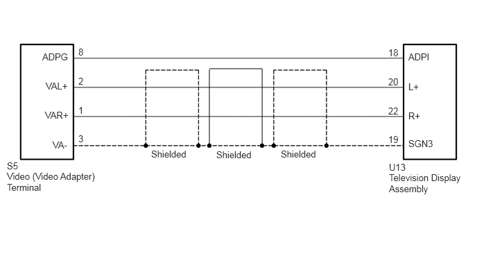
This is the sound signal circuit from the video (video adapter) terminal to the television display assembly.
WIRING DIAGRAM
3.938,1.031 3.146,1.031
false
3.146,1.042 3.146,2.177
false
3.938,1.031 3.938,2.177
false
0.104,2.406 0.552,2.583
0.448,0.177
10
false
S5
1.177,0.698 1.406,0.875
0.229,0.177
10
false
8
0.635,0.771 1.083,0.948
0.448,0.177
10
false
ADPG
0.677,1.646 1.083,1.823
0.406,0.177
10
false
VAR+
0.688,1.208 1.083,1.385
0.396,0.177
10
false
VAL+
0.792,2.094 1.094,2.271
0.302,0.177
10
false
VA-
6.135,0.771 6.583,0.948
0.448,0.177
10
false
ADPI
6.135,1.656 6.542,1.833
0.406,0.177
10
false
R+
6.135,1.219 6.531,1.396
0.396,0.177
10
false
L+
6.135,2.073 6.604,2.25
0.469,0.177
10
false
SGN3
1.177,1.573 1.375,1.75
0.198,0.177
10
false
1
1.177,1.135 1.375,1.313
0.198,0.177
10
false
2
1.177,2 1.375,2.177
0.198,0.177
10
false
3
5.833,0.708 6.063,0.885
0.229,0.177
10
false
18
5.833,1.583 6.031,1.76
0.198,0.177
10
false
22
5.833,1.146 6.031,1.323
0.198,0.177
10
false
20
5.833,2.01 6.031,2.188
0.198,0.177
10
false
19
0.104,2.563 1.51,3.188
1.406,0.625
10
false
Video (Video Adapter) Terminal
5.844,2.427 6.292,2.604
0.448,0.177
10
false
U13
5.844,2.583 7.021,3.115
1.177,0.531
10
false
Television Display Assembly
2.271,2.229 3.052,2.406
0.781,0.177
10
false
Shielded
3.25,2.24 4.031,2.417
0.781,0.177
10
false
Shielded
4.219,2.229 5,2.406
0.781,0.177
10
false
Shielded
PROCEDURE
1.CHECK HARNESS AND CONNECTOR (TELEVISION DISPLAY ASSEMBLY - VIDEO [VIDEO ADAPTER] TERMINAL)
a.
Disconnect the U13 television display assembly connector.
b.
Disconnect the S5 (video adapter) video terminal connector.
c.
Measure the resistance according to the value(s) in the table below.
- Standard Resistance:
Tester Connection Condition Specified Condition U13-18 (ADPI) - S5-8 (ADPG) Always Below 1 Ω U13-22 (R+) - S5-1 (VAR+) Always Below 1 Ω U13-20 (L+) - S5-2 (VAL+) Always Below 1 Ω U13-19 (SGN3) - S5-3 (VA-) Always Below 1 Ω U13-18 (ADPI) - Body ground Always 10 kΩ or higher U13-22 (R+) - Body ground Always 10 kΩ or higher U13-20 (L+) - Body ground Always 10 kΩ or higher U13-19 (SGN3) - Body ground Always 10 kΩ or higher
OK
2.CHECK VIDEO (VIDEO ADAPTER) TERMINAL
NG
REPAIR OR REPLACE HARNESS OR CONNECTOR
2.CHECK VIDEO (VIDEO ADAPTER) TERMINAL
a.
0.896,2.281 1.385,1.792
false
1.01,2.281 1.385,2.281
false
0.208,2.177 0.49,2.344
0.281,0.167
10
false
S5
1.406,1.688 1.802,1.854
0.396,0.167
10
false
VAL+
1.406,2.198 1.844,2.365
0.438,0.167
10
false
VAR+
0.115,0.052 2.427,0.458
2.313,0.406
10
false
*a
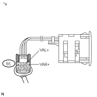
Remove the video (video adapter) terminal connector still connected (See page Vehicle Interior>INTERIOR PANELS / TRIM>FRONT CONSOLE BOX>DISASSEMBLY).
b.
Using an oscilloscope, check the waveform between each terminal and the body ground according to the conditions as shown in the table below.
- Standard:
Tester Connection Condition Specified Condition S5-1 (VAR+) - Body ground External device playing, sound being produced Waveform synchronized with sound is output S5-2 (VAL+) - Body ground
| *a | Component with harness connected
(Video [Video Adapter] Terminal) |
OK
PROCEED TO NEXT SUSPECTED AREA SHOWN IN PROBLEM SYMPTOMS TABLE
(See pageAudio / Visual / Telematics>AUDIO / VIDEO>REAR SEAT ENTERTAINMENT SYSTEM>PROBLEM SYMPTOMS TABLE)
NG
REPLACE VIDEO (VIDEO ADAPTER) TERMINAL