Home › Audio / Visual / Telematics › NAVIGATION / MULTI INFO DISPLAY › NAVIGATION SYSTEM
RM27L0U _56 Audio / Visual / Telematics _049330 NAVIGATION / MULTI INFO DISPLAY _0235785 NAVIGATION SYSTEM J

NAVIGATION / MULTI INFO DISPLAY  NAVIGATION SYSTEM  AVC-LAN Circuit  


DESCRIPTION

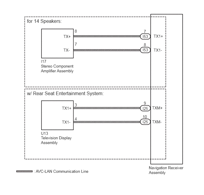
Each unit of the navigation system connected to the AVC-LAN (communication bus) transfers the switch signals using the AVC-LAN.

If a short to +B or short to ground occurs in the AVC-LAN, the navigation system will not function normally because communication is not possible.

WIRING DIAGRAM
E282598E02
1.438,4.604 1.885,4.771 0.448,0.167 10 false U13 2.625,3.604 2.823,3.771 0.198,0.167 10 false 3 2.625,4.094 2.823,4.26 0.198,0.167 10 false 4 2.177,4.208 2.552,4.375 0.375,0.167 10 false TX1- 2.177,3.719 2.552,3.885 0.375,0.167 10 false TX1+ 1.438,4.76 2.729,5.448 1.292,0.688 10 false Television Display Assembly 1.438,2.073 1.885,2.24 0.448,0.167 10 false I17 5.01,4.198 5.385,4.365 0.375,0.167 10 false I25 5.01,3.729 5.385,3.896 0.375,0.167 10 false I25 5.01,4.021 5.208,4.188 0.198,0.167 10 false 10 5.052,3.542 5.25,3.708 0.198,0.167 10 false 9 5.344,4.198 5.865,4.365 0.521,0.167 10 false TXM- 5.344,3.708 5.885,3.875 0.542,0.167 10 false TXM+ 5.01,1.667 5.385,1.833 0.375,0.167 10 false I53 5.01,1.198 5.385,1.365 0.375,0.167 10 false I53 2.625,1.01 2.823,1.177 0.198,0.167 10 false 8 2.625,1.469 2.823,1.635 0.198,0.167 10 false 7 5.052,1.49 5.25,1.656 0.198,0.167 10 false 8 5.052,1.021 5.25,1.188 0.198,0.167 10 false 7 2.229,1.677 2.604,1.844 0.375,0.167 10 false TX- 2.229,1.198 2.604,1.365 0.375,0.167 10 false TX+ 0.948,0.635 2.844,0.906 1.896,0.271 12 false for 14 Speakers: 5.396,1.677 5.771,1.844 0.375,0.167 10 false TX1- 5.396,1.188 5.771,1.354 0.375,0.167 10 false TX1+ 5.229,5.813 6.521,6.208 1.292,0.396 10 false Navigation Receiver Assembly 1.188,5.938 4.396,6.146 3.208,0.208 10 false : AVC-LAN Communication Line 1.438,2.24 2.74,2.865 1.302,0.625 10 false Stereo Component Amplifier Assembly 0.948,3.177 3.813,3.438 2.865,0.26 12 false w/ Rear Seat Entertainment System:

CAUTION / NOTICE / HINT

HINT:

The navigation receiver assembly is the master unit.


PROCEDURE
1.INSPECT NAVIGATION RECEIVER ASSEMBLY
E259251E03
1.198,1.573 1.281,1.573 1.281,1.573 1.635,1.042 true 2.198,1.573 2.115,1.573 2.115,1.573 1.771,1.042 true 1.375,3.104 1.458,3.104 1.458,3.104 1.635,2.74 true 2.031,3.115 1.948,3.115 1.948,3.115 1.771,2.75 true 0.823,1.49 1.313,1.667 0.49,0.177 10 false TX1- 0.146,0.115 0.635,0.292 0.49,0.177 10 false *A 0.135,1.865 0.625,2.042 0.49,0.177 10 false *B 2.24,1.479 2.729,1.656 0.49,0.177 10 false TX1+ 0.99,3.021 1.479,3.198 0.49,0.177 10 false TXM- 2.063,3.021 2.552,3.198 0.49,0.177 10 false TXM+

a.

Remove the navigation receiver assembly with the connector(s) still connected (See page Audio / Visual / Telematics>NAVIGATION / MULTI INFO DISPLAY>NAVIGATION RECEIVER>REMOVAL).


b.

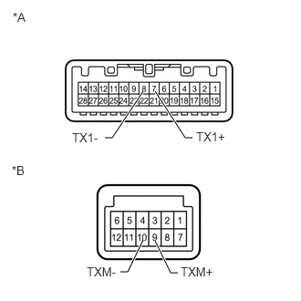
Measure the resistance according to the value(s) in the table below.

Standard Resistance:
Tester Connection Condition Specified Condition
7 (TX1+) - 8 (TX1-) Always 60 to 80 Ω
9 (TXM+) - 10 (TXM-) Always 60 to 80 Ω


Text in Illustration
*A for 14 Speakers
*B w/ Rear Seat Entertainment System


OK

2.CHECK HARNESS AND CONNECTOR (AVC-LAN CIRCUIT)

NG

2.CHECK HARNESS AND CONNECTOR (AVC-LAN CIRCUIT)

*1: for 14 Speakers

*2: w/ Rear Seat Entertainment System


a.

Disconnect the I53*1 and/or I25*2 navigation receiver assembly connector.


b.

Disconnect the I17 stereo component amplifier assembly connector.*1


c.

Disconnect the U13 television display assembly connector.*2


d.

Measure the resistance according to the value(s) in the table below.

Standard Resistance:
Tester Connection Condition Specified Condition
I17-8 (TX+) - I53-7 (TX1+)*1 Always Below 1 Ω
I17-7 (TX-) - I53-8 (TX1-)*1 Always Below 1 Ω
U13-3 (TX1+) - I25-9 (TXM+)*2 Always Below 1 Ω
U13-4 (TX1-) - I25-10 (TXM-)*2 Always Below 1 Ω
I17-8 (TX+) - Body ground*1 Always 10 kΩ or higher
I17-7 (TX-) - Body ground*1 Always 10 kΩ or higher
U13-3 (TX1+) - Body ground*2 Always 10 kΩ or higher
U13-4 (TX1-) - Body ground*2 Always 10 kΩ or higher


OK

3.INSPECT MALFUNCTIONING PARTS

NG

REPAIR OR REPLACE HARNESS OR CONNECTOR

3.INSPECT MALFUNCTIONING PARTS
a.

Disconnect and reconnect each slave unit one by one until the master unit returns to normal operation.

HINT:
·

Check all slave units.

·

If disconnecting a slave unit causes the master unit to return to normal operation, the slave unit is defective and should be replaced.


OK:

Master unit returns to normal operation.


OK

REPLACE MALFUNCTIONING PARTS

NG