NAVIGATION / MULTI INFO DISPLAY NAVIGATION SYSTEM B15FE XM Tuner Antenna Disconnected B15FF XM Tuner Antenna Short
DESCRIPTION
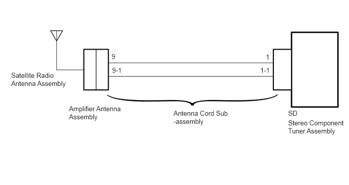
These DTCs are stored when a malfunction occurs in the satellite radio antenna which is connected to the navigation receiver assembly.
| DTC Code | DTC Detection Condition | Trouble Area |
|---|---|---|
| B15FE | Satellite radio antenna is not connected. | ·
Satellite radio antenna assembly ·
Amplifier antenna assembly ·
Antenna cord sub-assembly ·
Stereo component tuner assembly ·
Navigation receiver assembly |
| B15FF | A short occurs in satellite radio antenna. |
WIRING DIAGRAM
CAUTION / NOTICE / HINT
- NOTICE:
- ·
Some satellite radio broadcasts require payment. A contract must be made between a satellite radio company and the user. If the contract expires, it will not be possible to listen to the broadcast.
·After replacing the stereo component tuner assembly of vehicles subscribed to pay-type satellite radio broadcasts, XM radio ID registration is necessary.
PROCEDURE
Check if the satellite radio antenna cable is securely connected to the stereo component tuner assembly.
- OK:
Satellite radio antenna cable is securely connected.
OK
NG
Disconnect the stereo component tuner assembly connector.
Disconnect the antenna connector from the amplifier antenna assembly.
Measure the resistance according to the value(s) in the table below.
- Standard Resistance:
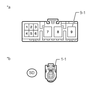
Tester Connection Condition Specified Condition SD-1 - 9 Always Below 1 Ω SD-1-1 - 9-1 Always Below 1 Ω SD-1 - Body ground Always 10 kΩ or higher SD-1-1 - Body ground Always 10 kΩ or higher
| *a | Front view of wire harness connector
(to Amplifier Antenna Assembly) |
| *b | Front view of wire harness connector
(to Stereo Component Tuner Assembly) |
OK
NG
Replace the satellite radio antenna assembly with a known good one (See page Audio / Visual / Telematics>AUDIO / VIDEO>SATELLITE RADIO ANTENNA>REMOVAL).
Clear the DTCs (See page Audio / Visual / Telematics>NAVIGATION / MULTI INFO DISPLAY>NAVIGATION SYSTEM>DTC CHECK / CLEAR).
Check for DTCs (See page Audio / Visual / Telematics>NAVIGATION / MULTI INFO DISPLAY>NAVIGATION SYSTEM>DTC CHECK / CLEAR).
- OK:
No DTCs are output.
OK
NG
Replace the amplifier antenna assembly.
Check if radio broadcasts can be received normally.
- OK:
Radio broadcasts can be received normally.
OK
NG
Replace the stereo component tuner assembly with a known good one (See page Audio / Visual / Telematics>AUDIO / VIDEO>SATELLITE RADIO TUNER>REMOVAL).
Clear the DTCs (See page Audio / Visual / Telematics>NAVIGATION / MULTI INFO DISPLAY>NAVIGATION SYSTEM>DTC CHECK / CLEAR).
Check for DTCs (See page Audio / Visual / Telematics>NAVIGATION / MULTI INFO DISPLAY>NAVIGATION SYSTEM>DTC CHECK / CLEAR).
- OK:
No DTCs are output.
OK
NG