Home › Power Source / Network › 3UR-FBE BATTERY / CHARGING › GENERATOR
RM27L0U _57 Power Source / Network _049333 3UR-FBE BATTERY / CHARGING _0235799 GENERATOR A

3UR-FBE BATTERY / CHARGING  GENERATOR  DISASSEMBLY  


PROCEDURE

Hide 27411 1.REMOVE GENERATOR PULLEY

A187035E06
3.073,1.229 3.073,0.573 false 2.427,1.521 2.427,1.365 2.427,1.365 2.833,0.719 false 0.927,1.333 1.219,1.563 0.292,0.229 10 true Turn 1.667,1.854 1.979,2 0.313,0.146 10 false Hold 2.125,1.542 2.719,1.719 0.594,0.177 10 false SST 1-B 2.76,1.25 3.313,1.396 0.552,0.146 10 false SST 1-A

SST
09820-63011  (09820-06010, 09820-06021)

HINT:
SST 1-A and B 09820-06010
SST 2 09820-06021


a.

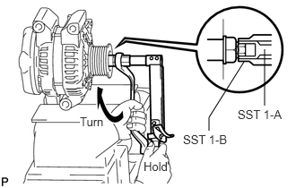
Clamp the generator housing stay in a vise.


b.

Hold SST 1-A with a torque wrench, and tighten SST 1-B clockwise to the specified torque.

Torque:
39 N*m (398 kgf*cm, 29 ft.*lbf)

NOTICE:

Check that SST is secured on the rotor shaft.


c.
A187036E05
2.563,0.427 2.688,0.427 2.688,0.427 2.792,0.885 false 2.031,0.333 2.469,0.552 0.438,0.219 10 false SST 2 2.375,1.354 2.76,1.552 0.385,0.198 10 true Insert

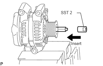
Insert SST 2, and attach the pulley nut to SST 2.

d.
A187037E05
2.979,0.719 3.292,0.865 0.313,0.146 10 false Turn 1.708,1.698 2.052,1.906 0.344,0.208 10 true Hold

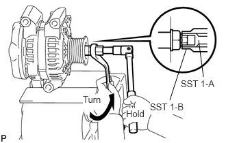
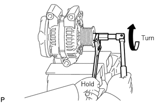
To loosen the pulley nut, turn SST 1-A in the direction shown in the illustration.

NOTICE:

To prevent damage to the rotor shaft, do not loosen the pulley nut more than one-half turn.


e.

Remove the generator from SST 2.


f.
A187038E09
3.094,1.177 3.021,0.615 false 2.583,1.531 2.833,0.75 false 1.26,1.438 1.552,1.688 0.292,0.25 10 true Turn 1.917,1.656 2.24,1.865 0.323,0.208 10 true Hold 2.281,1.552 2.865,1.75 0.583,0.198 10 true SST 1-B 2.75,1.198 3.302,1.354 0.552,0.156 10 false SST 1-A

Turn SST 1-B, and remove SST 1-A and B.


g.

Remove the pulley nut and pulley.


Hide 27039 2.REMOVE GENERATOR REAR END COVER
a.
A163586

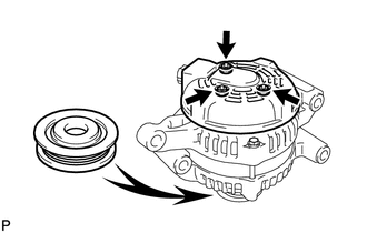
Place the generator on the pulley.


b.

Remove the 3 nuts and end cover.


c.
A156408

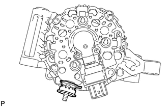
Remove the terminal insulator.


Hide 27370 3.REMOVE GENERATOR BRUSH HOLDER ASSEMBLY
a.
A156409

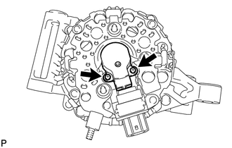
Remove the 2 screws and brush holder.


Hide 27360 4.REMOVE GENERATOR COIL ASSEMBLY
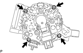
a.
A156414

Remove the 4 bolts.


b.
A156415E10
1.354,0.823 0.75,0.469 false 0.469,0.344 0.781,0.542 0.313,0.198 10 false SST 2.896,0.531 3.271,0.729 0.375,0.198 10 false Turn 0.25,1.563 0.625,1.76 0.375,0.198 10 false Hold

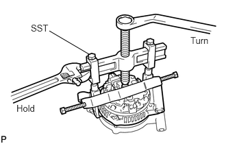
Using SST, remove the coil assembly.

SST
09950-40011  (09951-04020, 09952-04010, 09953-04020, 09954-04010, 09955-04071, 09957-04010, 09958-04011)


c.

Remove the generator washer.


Hide 27330 5.REMOVE GENERATOR ROTOR ASSEMBLY