RM27L0U
_57
Power Source / Network
_049335
NETWORKING
_0235802
CAN COMMUNICATION SYSTEM
U
NETWORKING CAN COMMUNICATION SYSTEM SYSTEM DIAGRAM
SYSTEM DIAGRAM
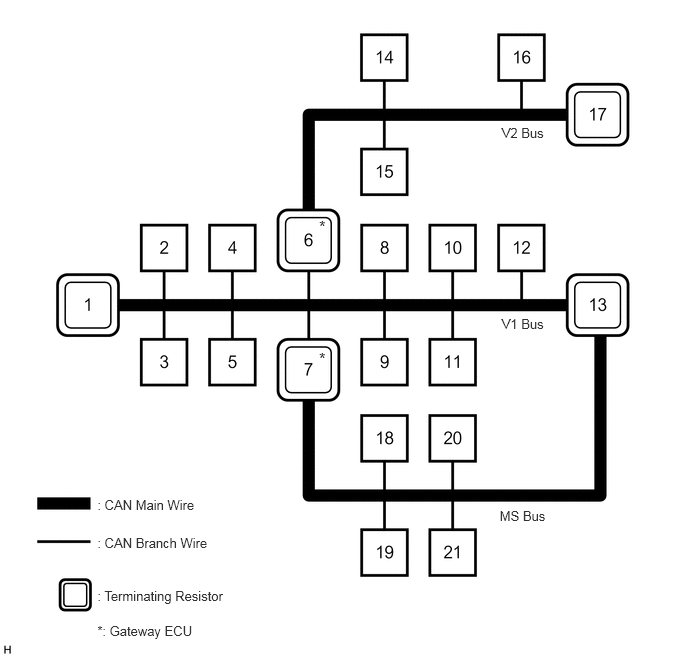
1.014,5.179 2.941,5.321
1.927,0.142
10
: CAN Main Wire
1.014,5.572 2.941,5.714
1.927,0.142
10
: CAN Branch Wire
1.014,6.129 2.632,6.277
1.618,0.147
10
: Terminating Resistor
1.014,6.494 2.632,6.641
1.618,0.147
10
*: Gateway ECU
5.205,5.291 5.722,5.433
0.517,0.142
10
MS Bus
5.226,1.298 5.702,1.440
0.475,0.142
10
V2 Bus
5.226,3.295 5.702,3.437
0.475,0.142
10
V1 Bus
3.323,3.638 3.442,3.799
0.119,0.161
12
*
3.323,2.265 3.442,2.426
0.119,0.161
12
*
| No. | ECU/Sensor Name |
|---|---|
| 1 | ECM |
| 2 | Air conditioning amplifier assembly |
| 3 | Bus buffer ECU*1 |
| 4 | 4 wheel drive control ECU (4WD control ECU)*2 |
| 5 | Steering angle sensor |
| 6 | Network gateway ECU*3 |
| 7 | Main body ECU (cowl side junction block LH) |
| 8 | Brake actuator assembly (skid control ECU) |
| 9 | Power steering ECU assembly |
| 10 | DCL3 |
| 11 | Center airbag sensor assembly |
| 12 | Suspension control ECU*4 |
| 13 | Combination meter assembly |
| 14 | Distance control ECU assembly*5 |
| 15 | Blind spot monitor sensor LH*6 |
| 16 | Blind spot monitor sensor RH*6 |
| 17 | No. 7 junction connector*3 |
| 18 | Power back door unit assembly (power back door ECU)*7 |
| 19 | Outer mirror control ECU assembly*8 |
| 20 | Multiplex tilt and telescopic ECU*8 |
| 21 | Front power seat switch LH (power seat control ECU)*8 |
*1: w/ Bus Buffer ECU
*2: for 4WD
*3: w/ Network Gateway ECU
*4: w/ Air Suspension System
*5: w/ Dynamic Laser Cruise Control System
*6: w/ Blind Spot Monitor Sensor
*7: w/ Power Back Door System
*8: w/ Seat Memory
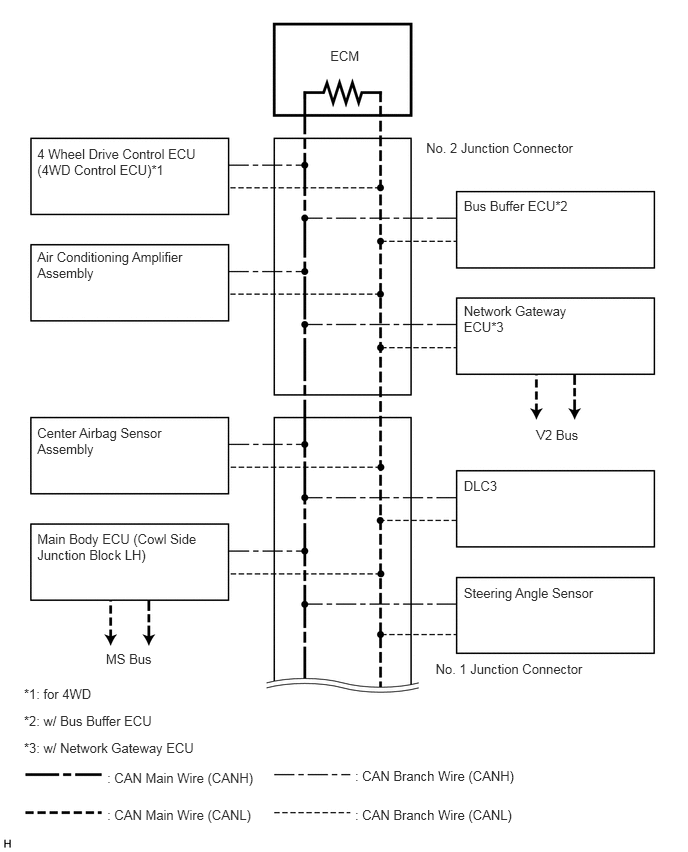
V1 BUS
3.44,0.502 3.780,0.675
0.340,0.173
10
ECM
1.116,8.023 2.869,8.165
1.753,0.142
10
: CAN Main Wire (CANH)
1.116,8.411 2.869,8.553
1.753,0.142
10
: CAN Main Wire (CANL)
0.249,7.706 2.204,7.848
1.955,0.142
10
*3: w/ Network Gateway ECU
0.249,7.142 0.995,7.284
0.746,0.142
10
*1: for 4WD
0.249,7.424 1.648,7.566
1.399,0.142
10
*2: w/ Bus Buffer ECU
3.698,8.005 5.451,8.147
1.753,0.142
10
: CAN Branch Wire (CANH)
3.698,8.411 5.451,8.553
1.753,0.142
10
: CAN Branch Wire (CANL)
0.388,1.518 2.118,1.840
1.730,0.323
10
4 Wheel Drive Control ECU (4WD Control ECU)*1
0.388,2.592 2.118,2.914
1.730,0.323
10
Air Conditioning Amplifier Assembly
4.831,2.058 5.978,2.210
1.147,0.152
10
Bus Buffer ECU*2
4.831,6.092 6.561,6.415
1.730,0.323
10
Steering Angle Sensor
0.388,4.431 2.002,4.759
1.614,0.327
10
Center Airbag Sensor Assembly
4.831,3.155 5.987,3.482
1.156,0.327
10
Network Gateway ECU*3
0.388,5.531 2.118,5.853
1.730,0.323
10
Main Body ECU (Cowl Side Junction Block LH)
4.831,4.975 6.445,5.302
1.614,0.327
10
DLC3
4.439,1.462 6.065,1.613
1.626,0.152
10
No. 2 Junction Connector
4.537,6.883 6.163,7.035
1.626,0.152
10
No. 1 Junction Connector
5.586,4.446 6.070,4.588
0.484,0.142
10
V2 Bus
1.103,6.786 1.624,6.928
0.521,0.142
10
MS Bus
1.122,5.256 2.875,5.398
1.753,0.142
10
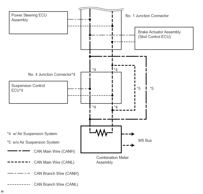
: CAN Main Wire (CANH)
1.122,5.648 2.875,5.790
1.753,0.142
10
: CAN Main Wire (CANL)
0.249,4.94 2.231,5.082
1.982,0.142
10
*5: w/o Air Suspension System
0.249,4.634 2.147,4.776
1.899,0.142
10
*4: w/ Air Suspension System
1.122,6.039 2.875,6.181
1.753,0.142
10
: CAN Branch Wire (CANH)
1.122,6.43 2.875,6.572
1.753,0.142
10
: CAN Branch Wire (CANL)
0.401,0.451 1.723,0.773
1.323,0.323
10
Power Steering ECU Assembly
4.876,1.037 6.469,1.373
1.593,0.336
10
Brake Actuator Assembly (Skid Control ECU)
0.401,2.935 1.659,3.257
1.258,0.323
10
Suspension Control ECU*4
3.399,5.478 4.618,5.799
1.218,0.321
10
Combination Meter Assembly
4.884,4.876 5.401,5.013
0.517,0.137
10
MS Bus
4.429,0.468 6.055,0.619
1.626,0.152
10
No. 1 Junction Connector
0.999,2.545 2.729,2.696
1.730,0.152
10
No. 4 Junction Connector*4
3.257,2.379 3.431,2.530
0.174,0.152
10
*4
4.024,2.379 4.198,2.530
0.174,0.152
10
*4
3.257,3.703 3.431,3.854
0.174,0.152
10
*4
4.024,3.703 4.198,3.854
0.174,0.152
10
*4
4.836,3.044 5.011,3.196
0.174,0.152
10
*5
5.295,3.044 5.470,3.196
0.174,0.152
10
*5
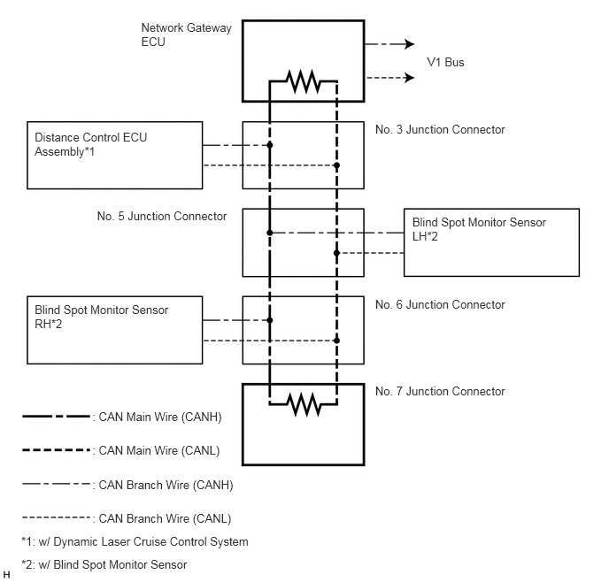
V2 BUS (w/ Network Gateway ECU)
1.087,4.818 2.840,4.960
1.753,0.142
10
: CAN Main Wire (CANH)
1.087,5.22 2.840,5.362
1.753,0.142
10
: CAN Main Wire (CANL)
0.251,6.295 3.040,6.438
2.790,0.143
10
*1: w/ Dynamic Laser Cruise Control System
0.251,6.559 3.040,6.702
2.790,0.143
10
*2: w/ Blind Spot Monitor Sensor
1.087,5.622 2.840,5.764
1.753,0.142
10
: CAN Branch Wire (CANH)
1.087,6.023 2.840,6.165
1.753,0.142
10
: CAN Branch Wire (CANL)
0.408,1.53 2.138,1.853
1.730,0.323
10
Distance Control ECU Assembly*1
0.408,3.566 2.101,3.889
1.693,0.323
10
Blind Spot Monitor Sensor RH*2
4.415,1.435 6.041,1.587
1.626,0.152
10
No. 3 Junction Connector
5.029,0.643 5.530,0.795
0.501,0.152
10
V1 Bus
4.415,3.496 6.041,3.648
1.626,0.152
10
No. 6 Junction Connector
4.415,4.524 6.041,4.675
1.626,0.152
10
No. 7 Junction Connector
1.141,2.456 2.767,2.608
1.626,0.152
10
No. 5 Junction Connector
1.661,0.235 2.790,0.540
1.128,0.306
10
Network Gateway ECU
4.852,2.527 6.545,2.850
1.693,0.323
10
Blind Spot Monitor Sensor LH*2
MS BUS (w/ Seat Memory)
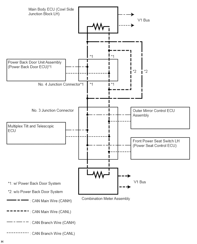
5.011,0.648 5.494,0.790
0.483,0.141
10
V1 Bus
4.871,6.533 5.354,6.674
0.483,0.141
10
V1 Bus
1.087,7.216 2.840,7.358
1.753,0.142
10
: CAN Main Wire (CANH)
1.087,7.615 2.840,7.757
1.753,0.142
10
: CAN Main Wire (CANL)
0.288,6.883 2.659,7.025
2.371,0.142
10
*2: w/o Power Back Door System
0.288,6.588 2.416,6.730
2.128,0.142
10
*1: w/ Power Back Door System
1.087,8.013 2.840,8.155
1.753,0.142
10
: CAN Branch Wire (CANH)
1.087,8.411 2.840,8.553
1.753,0.142
10
: CAN Branch Wire (CANL)
0.288,2.181 2.368,2.658
2.081,0.477
10
Power Back Door Unit Assembly (Power Back Door ECU)*1
0.288,4.498 2.048,4.821
1.760,0.323
10
Multiplex Tilt and Telescopic ECU
4.831,3.933 6.445,4.261
1.614,0.327
10
Outer Mirror Control ECU Assembly
4.831,5.047 6.650,5.529
1.819,0.482
10
Front Power Seat Switch LH (Power Seat Control ECU)
1.391,2.982 3.128,3.134
1.737,0.152
10
No. 4 Junction Connector*1
1.153,3.926 2.779,4.077
1.626,0.152
10
No. 3 Junction Connector
1.034,0.251 2.764,0.574
1.730,0.323
10
Main Body ECU (Cowl Side Junction Block LH)
4.037,1.972 4.236,2.114
0.199,0.141
10
*1
3.261,1.972 3.460,2.114
0.199,0.141
10
*1
4.037,2.982 4.236,3.124
0.199,0.141
10
*1
3.261,2.982 3.460,3.124
0.199,0.141
10
*1
5.242,2.512 5.441,2.653
0.199,0.141
10
*2
4.83,2.512 5.029,2.653
0.199,0.141
10
*2
2.971,7.136 4.897,7.278
1.927,0.142
10
Combination Meter Assembly