Home › Vehicle Interior › LIGHTING (INT) › LIGHTING SYSTEM
RM27L0U _58 Vehicle Interior _049338 LIGHTING (INT) _0235823 LIGHTING SYSTEM J

LIGHTING (INT)  LIGHTING SYSTEM  Door Courtesy Switch Circuit  


DESCRIPTION

The main body ECU receives a door open/closed signal from each door courtesy light switch.

WIRING DIAGRAM
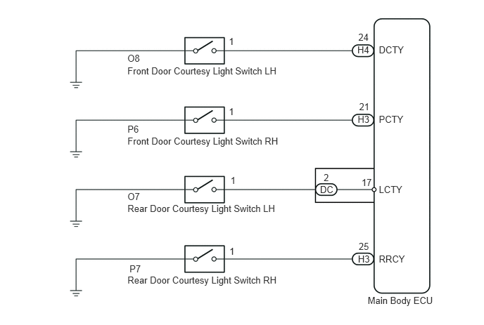
E157850E01
1.887,0.966 4.225,1.135 2.338,0.169 10 Front Door Courtesy Light Switch LH 1.888,4.073 4.226,4.241 2.338,0.169 10 Rear Door Courtesy Light Switch RH 1.888,3.009 4.226,3.178 2.338,0.169 10 Rear Door Courtesy Light Switch LH 1.888,2.009 4.226,2.177 2.338,0.169 10 Front Door Courtesy Light Switch RH 5.445,4.376 6.468,4.538 1.023,0.162 10 Main Body ECU 1.887,0.786 2.146,0.947 0.259,0.161 10 O8 3.389,0.532 3.490,0.702 0.101,0.170 10 1 5.292,0.652 5.502,0.811 0.210,0.159 10 H4 5.306,0.465 5.488,0.623 0.182,0.158 10 24 5.61,0.656 6.037,0.810 0.427,0.154 10 DCTY 1.888,1.833 2.087,1.985 0.199,0.152 10 P6 3.389,1.569 3.490,1.739 0.101,0.170 10 1 5.296,1.689 5.499,1.845 0.203,0.155 10 H3 5.318,1.499 5.491,1.661 0.174,0.163 10 21 5.61,1.685 6.015,1.853 0.405,0.168 10 PCTY 1.888,2.831 2.105,2.998 0.217,0.166 10 O7 3.413,2.59 3.514,2.756 0.101,0.166 10 1 4.739,2.725 4.982,2.880 0.243,0.155 10 DC 4.793,2.549 4.901,2.712 0.108,0.163 10 2 5.353,2.626 5.544,2.768 0.191,0.142 10 17 5.61,2.731 5.998,2.886 0.388,0.155 10 LCTY 1.918,3.905 2.208,4.064 0.290,0.159 10 P7 3.397,3.641 3.498,3.807 0.101,0.166 10 1 5.301,3.76 5.508,3.915 0.206,0.155 10 H3 5.311,3.577 5.483,3.727 0.172,0.150 10 25 5.61,3.761 6.061,3.920 0.451,0.159 10 RRCY

PROCEDURE

1.READ VALUE USING TECHSTREAM (DOOR COURTESY LIGHT SWITCH)
a.

Connect the Techstream to the DLC3.


b.

Turn the ignition switch to ON.


c.

Turn the Techstream on.


d.

Enter the following menus: Body Electrical / Main Body / Data List.


e.

According to the display on the Techstream, read the Data List.

Main Body
Tester Display Measurement Item/Range Normal Condition Diagnostic Note
D Door Courtesy SW Front door courtesy light switch LH signal / ON or OFF ON: Front door courtesy light switch LH ON
OFF: Front door courtesy light switch LH OFF
-
P Door Courtesy SW Front door courtesy light switch RH signal / ON or OFF ON: Front door courtesy light switch RH ON
OFF: Front door courtesy light switch RH OFF
-
RL Door Courtesy SW Rear door courtesy light switch LH signal / ON or OFF ON: Rear door courtesy light switch LH ON
OFF: Rear door courtesy light switch LH OFF
-
RR Door Courtesy SW Rear door courtesy light switch RH signal / ON or OFF ON: Rear door courtesy light switch RH ON
OFF: Rear door courtesy light switch RH OFF
-

Result
Result Proceed to
OK A
NG (Front door courtesy light switch LH does not operate) B
NG (Front door courtesy light switch RH does not operate) C
NG (Rear door courtesy light switch LH does not operate) D
NG (Rear door courtesy light switch RH does not operate) E


A

PROCEED TO NEXT CIRCUIT INSPECTION SHOWN IN PROBLEM SYMPTOMS TABLE

B

2.INSPECT FRONT DOOR COURTESY LIGHT SWITCH LH

C

4.INSPECT FRONT DOOR COURTESY LIGHT SWITCH RH

D

6.INSPECT REAR DOOR COURTESY LIGHT SWITCH LH

E

8.INSPECT REAR DOOR COURTESY LIGHT SWITCH RH
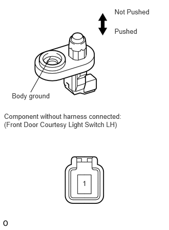
2.INSPECT FRONT DOOR COURTESY LIGHT SWITCH LH
E142907E15
1.679,3.644 1.779,3.800 0.100,0.156 10 1 2.329,0.557 2.985,0.713 0.656,0.156 10 Pushed 2.329,0.156 3.156,0.312 0.827,0.156 10 Not Pushed 0.082,2.286 2.784,2.623 2.702,0.336 10 Component without harness connected: (Front Door Courtesy Light Switch LH) 0.241,1.866 1.049,2.036 0.809,0.170 10 Body ground 1.031,1.147 0.624,1.875 false

a.

Remove the front door courtesy light switch LH (See page Vehicle Interior>LIGHTING (INT)>FRONT DOOR COURTESY SWITCH>REMOVAL).


b.

Measure the resistance according to the value(s) in the table below.

Standard Resistance:
Tester Connection Switch Condition Specified Condition
1 - Body ground Not pushed Below 1 Ω
Pushed 10 kΩ or higher


c.

Reinstall the front door courtesy light switch LH.


OK

3.CHECK HARNESS AND CONNECTOR (FRONT DOOR COURTESY LIGHT SWITCH LH - MAIN BODY ECU)

NG

REPLACE FRONT DOOR COURTESY LIGHT SWITCH LH

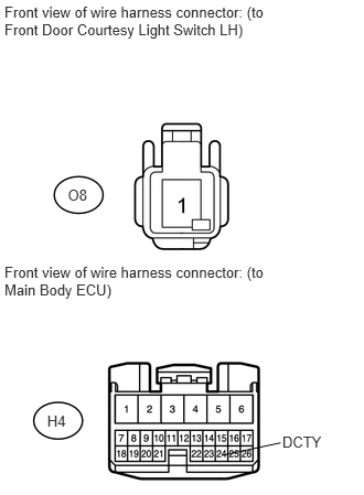
3.CHECK HARNESS AND CONNECTOR (FRONT DOOR COURTESY LIGHT SWITCH LH - MAIN BODY ECU)
U153977E01
0.042,0.034 2.576,0.375 2.534,0.341 10 Front view of wire harness connector: (to Front Door Courtesy Light Switch LH) 0.042,2.486 2.576,2.827 2.534,0.341 10 Front view of wire harness connector: (to Main Body ECU) 0.446,3.897 0.646,4.062 0.200,0.165 10 H4 0.64,1.76 0.857,1.925 0.217,0.165 10 O8 2.095,4.301 2.649,4.184 false 2.666,4.098 3.081,4.249 0.415,0.151 10 DCTY

a.

Disconnect the O8 front door courtesy light switch LH connector.


b.

Disconnect the H4 main body ECU connector.


c.

Measure the resistance according to the value(s) in the table below.

Standard Resistance:
Tester Connection Condition Specified Condition
O8-1 - H4-24 (DCTY) Always Below 1 Ω
O8-1 - Body ground Always 10 kΩ or higher


d.

Reconnect the main body ECU connector.


e.

Reconnect the front door courtesy light switch LH connector.


OK

REPLACE MAIN BODY ECU

NG

REPAIR OR REPLACE HARNESS OR CONNECTOR

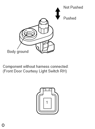
4.INSPECT FRONT DOOR COURTESY LIGHT SWITCH RH
E142907E16
1.661,3.627 1.762,3.782 0.100,0.156 10 1 2.295,0.574 2.950,0.730 0.656,0.156 10 Pushed 2.295,0.173 3.122,0.329 0.827,0.156 10 Not Pushed 0.099,2.326 2.588,2.662 2.489,0.336 10 Component without harness connected: (Front Door Courtesy Light Switch RH) 0.261,1.777 1.069,1.947 0.809,0.170 10 Body ground 1.006,1.147 0.624,1.783 false

a.

Remove the front door courtesy light switch RH (See page Vehicle Interior>LIGHTING (INT)>FRONT DOOR COURTESY SWITCH>REMOVAL).


b.

Measure the resistance according to the value(s) in the table below.

Standard Resistance:
Tester Connection Switch Condition Specified Condition
1 - Body ground Not pushed Below 1 Ω
Pushed 10 kΩ or higher


c.

Reinstall the front door courtesy light switch RH.


OK

5.CHECK HARNESS AND CONNECTOR (FRONT DOOR COURTESY LIGHT SWITCH RH - MAIN BODY ECU)

NG

REPLACE FRONT DOOR COURTESY LIGHT SWITCH RH

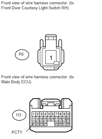
5.CHECK HARNESS AND CONNECTOR (FRONT DOOR COURTESY LIGHT SWITCH RH - MAIN BODY ECU)
U153979E01
0.042,0.015 2.627,0.356 2.585,0.341 10 Front view of wire harness connector: (to Front Door Courtesy Light Switch RH) 0.042,2.502 2.576,2.843 2.534,0.341 10 Front view of wire harness connector: (to Main Body ECU) 0.546,3.781 0.765,3.946 0.218,0.165 10 H3 0.631,1.737 0.835,1.902 0.205,0.165 10 P6 0.392,4.365 0.806,4.517 0.415,0.151 10 PCTY 0.884,4.44 1.137,4.144 false

a.

Disconnect the P6 front door courtesy light switch RH connector.


b.

Disconnect the H3 main body ECU connector.


c.

Measure the resistance according to the value(s) in the table below.

Standard Resistance:
Tester Connection Condition Specified Condition
P6-1 - H3-21 (PCTY) Always Below 1 Ω
P6-1 - Body ground Always 10 kΩ or higher


d.

Reconnect the main body ECU connector.


e.

Reconnect the front door courtesy light switch RH connector.


OK

REPLACE MAIN BODY ECU

NG

REPAIR OR REPLACE HARNESS OR CONNECTOR

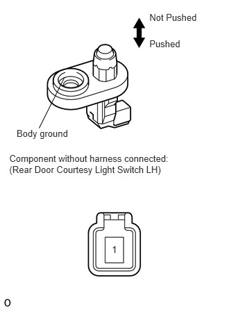
6.INSPECT REAR DOOR COURTESY LIGHT SWITCH LH
E142907E17
1.679,3.661 1.779,3.817 0.100,0.156 10 1 2.243,0.574 2.899,0.730 0.656,0.156 10 Pushed 2.243,0.173 3.070,0.329 0.827,0.156 10 Not Pushed 0.14,2.293 2.630,2.629 2.489,0.336 10 Component without harness connected: (Rear Door Courtesy Light Switch LH) 0.249,1.921 1.058,2.090 0.809,0.170 10 Body ground 0.968,1.159 0.587,1.921 false

a.

Remove the rear door courtesy light switch LH (See page Vehicle Interior>LIGHTING (INT)>REAR DOOR COURTESY SWITCH>REMOVAL).


b.

Measure the resistance according to the value(s) in the table below.

Standard Resistance:
Tester Connection Switch Condition Specified Condition
1 - Body ground Not pushed Below 1 Ω
Pushed 10 kΩ or higher


c.

Reinstall the rear door courtesy light switch LH.


OK

7.CHECK HARNESS AND CONNECTOR (REAR DOOR COURTESY LIGHT SWITCH LH - MAIN BODY ECU)

NG

REPLACE REAR DOOR COURTESY LIGHT SWITCH LH

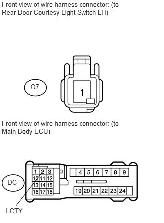
7.CHECK HARNESS AND CONNECTOR (REAR DOOR COURTESY LIGHT SWITCH LH - MAIN BODY ECU)
U153980E01
0.042,0.015 2.627,0.356 2.585,0.341 10 Front view of wire harness connector: (to Rear Door Courtesy Light Switch LH) 0.042,2.502 2.576,2.843 2.534,0.341 10 Front view of wire harness connector: (to Main Body ECU) 0.159,3.741 0.378,3.906 0.218,0.165 10 DC 0.64,1.742 0.859,1.907 0.218,0.165 10 O7 0.128,4.337 0.543,4.488 0.415,0.151 10 LCTY 0.34,4.308 0.899,3.595 false

a.

Disconnect the O7 rear door courtesy light switch LH connector.


b.

Disconnect the DC main body ECU connector.


c.

Measure the resistance according to the value(s) in the table below.

Standard Resistance:
Tester Connection Condition Specified Condition
O7-1 - DC-2 (LCTY) Always Below 1 Ω
O7-1 - Body ground Always 10 kΩ or higher


d.

Reconnect the main body ECU connector.


e.

Reconnect the rear door courtesy light switch LH connector.


OK

REPLACE MAIN BODY ECU

NG

REPAIR OR REPLACE HARNESS OR CONNECTOR

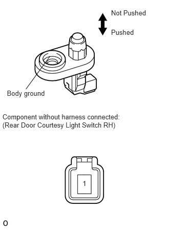
8.INSPECT REAR DOOR COURTESY LIGHT SWITCH RH
E142907E18
1.679,3.644 1.779,3.800 0.100,0.156 10 1 2.26,0.574 2.916,0.730 0.656,0.156 10 Pushed 2.26,0.173 3.087,0.329 0.827,0.156 10 Not Pushed 0.049,2.293 2.538,2.629 2.489,0.336 10 Component without harness connected: (Rear Door Courtesy Light Switch RH) 0.14,1.812 0.949,1.982 0.809,0.170 10 Body ground 1.017,1.141 0.527,1.812 false

a.

Remove the rear door courtesy light switch RH (See page Vehicle Interior>LIGHTING (INT)>REAR DOOR COURTESY SWITCH>REMOVAL).


b.

Measure the resistance according to the value(s) in the table below.

Standard Resistance:
Tester Connection Switch Condition Specified Condition
1 - Body ground Not pushed Below 1 Ω
Pushed 10 kΩ or higher


c.

Reinstall the rear door courtesy light switch RH.


OK

9.CHECK HARNESS AND CONNECTOR (REAR DOOR COURTESY LIGHT SWITCH RH - MAIN BODY ECU)

NG

REPLACE REAR DOOR COURTESY LIGHT SWITCH RH

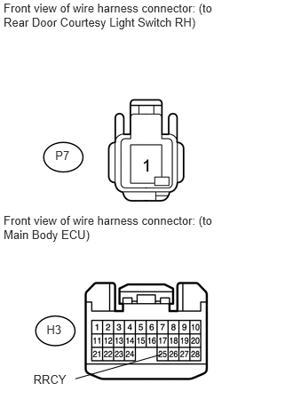
9.CHECK HARNESS AND CONNECTOR (REAR DOOR COURTESY LIGHT SWITCH RH - MAIN BODY ECU)
U153981E01
0.042,0.015 2.627,0.356 2.585,0.341 10 Front view of wire harness connector: (to Rear Door Courtesy Light Switch RH) 0.042,2.502 2.576,2.843 2.534,0.341 10 Front view of wire harness connector: (to Main Body ECU) 0.546,3.781 0.765,3.946 0.218,0.165 10 H3 0.648,1.737 0.948,1.902 0.300,0.165 10 P7 0.392,4.365 0.806,4.517 0.415,0.151 10 RRCY 0.884,4.44 1.897,4.153 false

a.

Disconnect the P7 rear door courtesy light switch RH connector.


b.

Disconnect the H3 main body ECU connector.


c.

Measure the resistance according to the value(s) in the table below.

Standard Resistance:
Tester Connection Condition Specified Condition
P7-1 - H3-25 (RRCY) Always Below 1 Ω
P7-1 - Body ground Always 10 kΩ or higher


d.

Reconnect the main body ECU connector.


e.

Reconnect the rear door courtesy light switch RH connector.


OK

REPLACE MAIN BODY ECU

NG

REPAIR OR REPLACE HARNESS OR CONNECTOR