RM27L0U
_58
Vehicle Interior
_049339
METER / GAUGE / DISPLAY
_0235842
DRIVE MONITOR SWITCH
G
METER / GAUGE / DISPLAY DRIVE MONITOR SWITCH INSPECTION
PROCEDURE

 84977
1.INSPECT DRIVE MONITOR SWITCH
a.
0.196,0.094 2.671,0.437
2.475,0.343
10
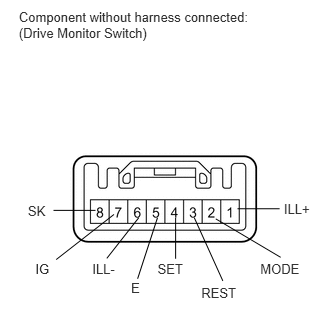
Component without harness connected: (Drive Monitor Switch)
0.29,2.116 0.495,2.279
0.205,0.163
10
SK
0.995,2.191 0.557,2.191
false
0.368,2.714 0.558,2.869
0.191,0.156
10
IG
0.961,2.714 1.244,2.869
0.283,0.156
10
ILL-
1.365,2.921 1.521,3.084
0.156,0.163
10
E
1.641,2.714 1.951,2.876
0.310,0.163
10
SET
2.097,2.967 2.505,3.130
0.408,0.163
10
REST
2.711,2.714 3.161,2.897
0.450,0.184
10
MODE
2.957,2.093 3.273,2.249
0.316,0.156
10
ILL+
2.912,2.174 2.473,2.174
false
2.247,2.279 2.923,2.68
false
2.023,2.267 2.321,2.926
false
1.829,2.267 1.829,2.695
false
1.64,2.267 1.433,2.903
false
1.445,2.267 1.112,2.691
false
1.187,2.233 0.585,2.703
false
Measure the resistance according to the value(s) in the table below.
- Standard Resistance:
Tester Connection Switch Condition Specified Condition 2 (MODE) - 5 (E) Info switch off 10 kΩ or higher Info switch on Below 1 Ω 3 (REST) - 5 (E) Select reset switch off 10 kΩ or higher Select reset switch on Below 1 Ω 4 (SET) - 5 (E) Setup us/m switch off 10 kΩ or higher Setup us/m switch on Below 1 Ω 7 (IG) - 8 (SK) Sonar switch off 10 kΩ or higher Sonar switch on Below 1 Ω
If the result is not as specified, replace the monitor switch.
b.
Inspect the switch illumination.
i.
Connect the positive (+) lead from the battery to terminal 1 (ILL+) and the negative (-) lead to terminal 6 (ILL-), and then check the Drive Monitor Switch.
- OK:
Switch illuminate.