RM27L0U
_58
Vehicle Interior
_049341
SUPPLEMENTAL RESTRAINT SYSTEMS
_0235847
OCCUPANT CLASSIFICATION SYSTEM
U
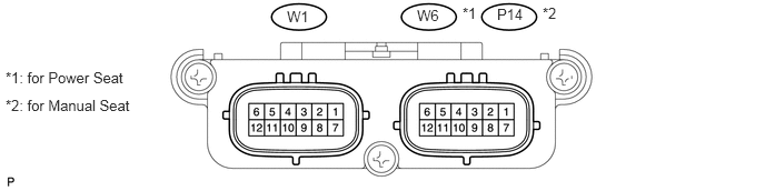
SUPPLEMENTAL RESTRAINT SYSTEMS OCCUPANT CLASSIFICATION SYSTEM TERMINALS OF ECU
CHECK OCCUPANT CLASSIFICATION ECU
4.656,0.052 4.958,0.229
0.302,0.177
10
false
P14
4.333,0.042 4.531,0.219
0.198,0.177
10
false
*1
2.688,0.073 2.99,0.25
0.302,0.177
10
false
W1
0.052,0.646 1.427,0.823
1.375,0.177
10
false
*1: for Power Seat
0.052,0.906 1.427,1.083
1.375,0.177
10
false
*2: for Manual Seat
3.906,0.063 4.188,0.24
0.281,0.177
10
false
W6
5.083,0.042 5.281,0.219
0.198,0.177
10
false
*2
| Terminal No. (Symbol) | Wiring Color | Terminal Description | Condition | Specified Condition |
|---|---|---|---|---|
| W6-1 (+B) - W6-3 (GND)*1
P14-1 (+B) - P14-3 (GND)*2 |
G - W-B*1
R - W-B*2 |
Battery | Ignition switch ON | 11 to 14 V |
| W6-2 (DIA) - W6-3 (GND)*1
P14-2 (DIA) - P14-3 (GND)*2 |
BR - W-B | Diagnosis (DLC3) | Ignition switch ON | Pulse generation |
| W6-3 (GND) - Body ground*1
P14-3 (GND) - Body ground*2 |
W-B - Body ground | Ground | Always | Below 1 Ω |
| W6-4- (FSR-) - W6-3 (GND)*1
P14-4- (FSR-) - P14-3 (GND)*2 |
B - W-B | Center airbag sensor communication ground line | Always | Below 1 Ω |
| W6-5 (BGND) - W6-3 (GND)*1
P14-5 (BGND) - P14-3 (GND)*2 |
BE - W-B | Passenger side buckle switch ground line | Always | Below 1 Ω |
| W6-7 (IG) - W6-3 (GND)*1
P14-7 (IG) - P14-3 (GND)*2 |
SB - W-B*1, *2
LG - W-B*3 |
Power source (IGN fuse) | Ignition switch ON | 11 to 14 V |
| W6-8 (FSR+) - W6-4 (FSR-)*1
P14-8 (FSR+) - P14-4 (FSR-)*2 |
W - B | Center airbag sensor communication line | Ignition switch ON | Pulse generation |
| W6-9 (BSW) - W6-5 (BGND)*1
P14-9 (BSW) - P14-5 (BGND)*2 |
L - BE | Passenger side buckle switch line | Buckle switch ON | 0.12 to 0.18 A |
| Buckle switch OFF | 0.4 to 0.7 mA | |||
| W1-1 (SGD1) - W6-3 (GND)*1
W1-1 (SGD1) - P14-3 (GND)*2 |
Y - W-B | Front occupant detection sensor LH ground line | Always | Below 1 Ω |
| W1-2 (SGD2) - W6-3 (GND)*1
W1-2 (SGD2) - P14-3 (GND)*2 |
SB - W-B*1, *2
LG - W-B*3 |
Front occupant detection sensor RH ground line | Always | Below 1 Ω |
| W1-3 (SGD3) - W6-3 (GND)*1
W1-3 (SGD3) - P14-3 (GND)*2 |
L - W-B | Rear occupant detection sensor LH ground line | Always | Below 1 Ω |
| W1-4 (SGD4) - W6-3 (GND)*1
W1-4 (SGD4) - P14-3 (GND)*2 |
W - W-B | Rear occupant detection sensor RH ground line | Always | Below 1 Ω |
| W1-11 (SVC1) - W1-1 (SGD1) | P - Y | Front occupant detection sensor LH power supply line | Ignition switch ON, load is applied to front occupant detection sensor LH | 4.5 to 5.1 V |
| W1-12 (SVC2) - W1-2 (SGD2) | BR - SB*1, *2
BR - LG*3 |
Front occupant detection sensor RH power supply line | Ignition switch ON, load is applied to front occupant detection sensor RH | 4.5 to 5.1 V |
| W1-5 (SVC3) - W1-3 (SGD3) | R -L | Rear occupant detection sensor LH power supply line | Ignition switch ON, load is applied to rear occupant detection sensor LH | 4.5 to 5.1 V |
| W1-6 (SVC4) - W1-4 (SGD4) | B - W | Rear occupant detection sensor RH power supply line | Ignition switch ON, load is applied to rear occupant detection sensor RH | 4.5 to 5.1 V |
| W1-7 (SIG1) - W1-1 (SGD1) | BE - Y | Front occupant detection sensor LH signal line | Ignition switch ON, load is applied to front occupant detection sensor LH | Pulse generation |
| W1-8 (SIG2) - W1-2 (SGD2) | GR - SB*1, *2
GR - LG*3 |
Front occupant detection sensor RH signal line | Ignition switch ON, load is applied to front occupant detection sensor RH | Pulse generation |
| W1-9 (SIG3) - W1-3 (SGD3) | G - L | Rear occupant detection sensor LH signal line | Ignition switch ON, load is applied to rear occupant detection sensor LH | Pulse generation |
| W1-10 (SIG4) - W1-4 (SGD4) | V - W | Rear occupant detection sensor RH signal line | Ignition switch ON, load is applied to rear occupant detection sensor RH | Pulse generation |
- HINT:
-
*1: for Power Seat
-
*2: for Manual Seat
*3: for Power Seat (w/o Climate Control Seat)
If the result is not as specified, the ECU may have a malfunction.