Home › Vehicle Interior › SEAT › SEAT HEATER SWITCH(for Front Seat)
RM27L0U _58 Vehicle Interior _049342 SEAT _0235871 SEAT HEATER SWITCH(for Front Seat) G

SEAT  SEAT HEATER SWITCH(for Front Seat)  INSPECTION  


PROCEDURE

Hide 84751 1.INSPECT SEAT HEATER SWITCH LH
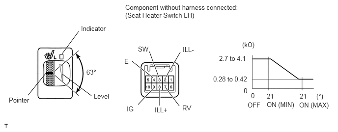
B443358E01
1.313,1.146 1.667,0.667 false 3.365,1.635 3.167,1.094 true 3.51,1.646 3.823,1.104 true 3.24,1.646 2.802,1.302 true 3.802,2.25 3.521,1.875 true 3.385,2.24 3.385,1.885 true 2.927,2.219 3.26,1.865 true 1.323,1.573 1.938,2.031 false 0.99,1.531 0.594,2.021 false 2.656,0.073 5.083,0.49 2.427,0.417 10 false Component without harness connected: (Seat Heater Switch LH) 2.927,0.958 3.188,1.135 0.26,0.177 10 false SW 3.875,0.969 4.135,1.146 0.26,0.177 10 false ILL- 2.635,1.219 2.781,1.396 0.146,0.177 10 false E 3.865,2.208 4.125,2.385 0.26,0.177 10 false RV 2.688,2.229 2.906,2.396 0.219,0.167 10 false IG 3.281,2.25 3.542,2.427 0.26,0.177 10 false ILL+ 1.719,0.521 2.271,0.719 0.552,0.198 10 false Indicator 1.833,1.448 2.094,1.635 0.26,0.188 10 false 63° 1.99,1.958 2.333,2.167 0.344,0.208 10 false Level 0.188,2.042 0.677,2.24 0.49,0.198 10 false Pointer 5.135,0.865 5.458,1.042 0.323,0.177 10 false (kΩ) 4.646,1.156 5.25,1.333 0.604,0.177 10 false 2.7 to 4.1 4.521,1.594 5.281,1.76 0.76,0.167 10 false 0.28 to 0.42 5.167,1.844 5.292,2.01 0.125,0.167 10 false 0 5.323,1.948 5.448,2.115 0.125,0.167 10 false 0 5.656,1.958 5.813,2.115 0.156,0.156 10 false 21 6.354,1.958 6.51,2.115 0.156,0.156 10 false 21 6.708,1.958 6.865,2.115 0.156,0.156 10 false (°) 5.25,2.146 5.521,2.333 0.271,0.188 10 false OFF 5.656,2.135 6.24,2.313 0.583,0.177 10 false ON (MIN) 6.344,2.146 6.99,2.323 0.646,0.177 10 false ON (MAX)

a.

Check the resistance.

i.

Measure the resistance according to the value(s) in the table below.

Standard Resistance:
Tester Connection Switch Condition Specified Condition
3 (SW) - 7 (RV) Switch OFF 2.7 to 4.1 kΩ
Switch ON (Min.)
Switch ON (Max.) 0.28 to 0.42 kΩ


HINT:

As the dial is being turned, the resistance changes gradually.


If the result is not as specified, replace the switch.


b.

Check the illumination operation.

i.

Apply battery voltage to the switch connector, and check that the seat heater switch LH illuminates.

OK:
Measurement Condition Switch Condition Specified Condition
Battery positive (+) → 8 (ILL+)
Battery negative (-) → 2 (ILL-)
Always Pointer and level
illuminate


If the result is not as specified, replace the switch.


c.

Check the indicator operation.

i.

Apply battery voltage to the switch connector, and check that the seat heater switch LH illuminates.

OK:
Measurement Condition Switch Condition Specified Condition
Battery positive (+) → 9 (IG)
Battery negative (-) → 4 (E)
Switch ON Indicator
illuminates


If the result is not as specified, replace the switch.


Hide 84751 2.INSPECT SEAT HEATER SWITCH RH

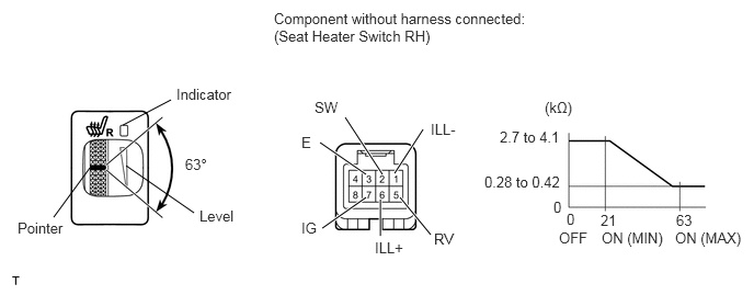
B443363E01
3.281,1.115 3.635,1.656 true 1.625,0.948 1.167,1.188 false 3.042,1.354 3.479,1.656 true 3.063,2.167 3.479,1.875 true 3.802,1.875 4.094,2.229 true 3.615,2.24 3.615,1.896 true 3.75,1.646 4.021,1.229 true 1.844,2.021 1.198,1.573 false 0.51,2.063 0.854,1.594 false 2.604,0.094 5.01,0.479 2.406,0.385 10 false Component without harness connected: (Seat Heater Switch RH) 1.677,0.813 2.24,1 0.563,0.188 10 false Indicator 2.99,0.938 3.25,1.094 0.26,0.156 10 false SW 2.865,1.271 2.99,1.448 0.125,0.177 10 false E 2.865,2.083 3.031,2.26 0.167,0.177 10 false IG 3.563,2.271 3.875,2.448 0.313,0.177 10 false ILL+ 4.094,1.146 4.406,1.323 0.313,0.177 10 false ILL- 4.125,2.188 4.375,2.385 0.25,0.198 10 false RV 5.177,0.938 5.531,1.125 0.354,0.188 10 false (kΩ) 4.75,1.219 5.365,1.396 0.615,0.177 10 false 2.7 to 4.1 4.604,1.646 5.365,1.823 0.76,0.177 10 false 0.28 to 0.42 5.26,1.885 5.365,2.063 0.104,0.177 10 false 0 5.385,2 5.49,2.177 0.104,0.177 10 false 0 5.708,2.01 5.875,2.188 0.167,0.177 10 false 21 6.427,2.01 6.594,2.188 0.167,0.177 10 false 63 5.313,2.177 5.604,2.365 0.292,0.188 10 false OFF 5.719,2.177 6.313,2.354 0.594,0.177 10 false ON (MIN) 6.417,2.177 7.063,2.365 0.646,0.188 10 false ON (MAX) 1.76,1.479 2.01,1.688 0.25,0.208 10 false 63° 1.896,1.969 2.229,2.188 0.333,0.219 10 false Level 0.167,2.083 0.625,2.292 0.458,0.208 10 false Pointer

a.

Check the resistance.

i.

Measure the resistance according to the value(s) in the table below.

Standard Resistance:
Tester Connection Switch Condition Specified Condition
2 (SW) - 5 (RV) Switch OFF 2.7 to 4.1 kΩ
Switch ON (Min.)
Switch ON (Max.) 0.28 to 0.42 kΩ


HINT:

As the dial is being turned, the resistance changes gradually.


If the result is not as specified, replace the switch.


b.

Check the illumination operation.

i.

Apply battery voltage to the switch connector, and check that the seat heater switch RH illuminates.

OK:
Measurement Condition Switch Condition Specified Condition
Battery positive (+) → 6 (ILL+)
Battery negative (-) → 1 (ILL-)
Always Pointer and level
illuminate


If the result is not as specified, replace the switch.


c.

Check the indicator operation.

i.

Apply battery voltage to the switch connector, and check that the seat heater switch RH illuminates.

OK:
Measurement Condition Switch Condition Specified Condition
Battery positive (+) → 7 (IG)
Battery negative (-) → 3 (E)
Switch ON Indicator
illuminates


If the result is not as specified, replace the switch.


Hide 84751 3.INSPECT SEAT HEATER AND CLIMATE SWITCH LH (w/ Climate Control Seat System)
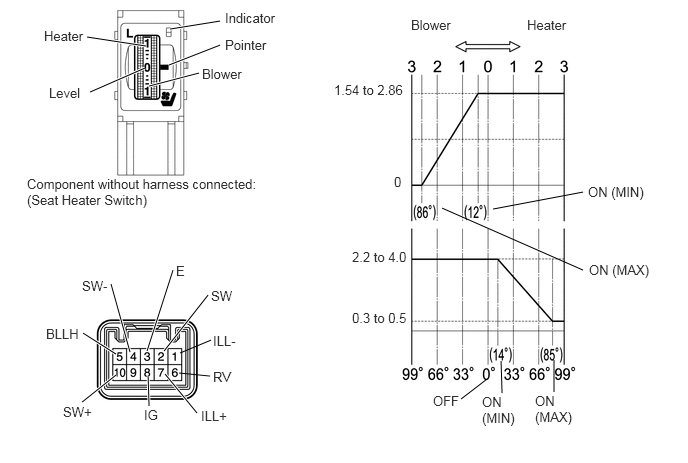
B194049E04
1.156,2.958 1.354,3.667 true 0.865,3.469 1.208,3.688 true 0.854,4.188 1.208,3.906 true 1.542,3.917 1.552,4.229 true 1.719,3.896 2.052,4.302 true 1.865,3.885 2.188,3.917 false 1.875,3.677 2.198,3.542 false 1.708,3.656 2.167,3.073 true 1.531,3.656 1.802,2.813 true 5.771,3.75 5.771,4.083 false 5.073,3.948 4.802,4.156 false 5.219,3.76 5.229,4.094 false 5.135,2.177 6.073,2 false 6.073,2.813 4.604,2.167 false 1.76,0.677 2.292,0.469 true 1.552,0.896 2.073,0.76 true 1.771,0.302 2.292,0.219 true 1.51,0.708 0.938,0.958 true 1.521,0.479 0.906,0.385 true 2.094,4.25 2.406,4.396 0.313,0.146 10 false ILL+ 2.219,3.469 2.49,3.635 0.271,0.167 10 false ILL- 2.198,3 2.469,3.156 0.271,0.156 10 false SW 0.479,3.396 0.865,3.563 0.385,0.167 10 false BLLH 0.656,4.208 1.01,4.365 0.354,0.156 10 false SW+ 0.854,2.896 1.177,3.042 0.323,0.146 10 false SW- 2.219,3.844 2.448,4.01 0.229,0.167 10 false RV 1.5,4.24 1.677,4.406 0.177,0.167 10 false IG 1.833,2.74 1.958,2.906 0.125,0.167 10 false E 4.281,0.177 4.729,0.333 0.448,0.156 10 false Blower 5.49,0.177 5.938,0.323 0.448,0.146 10 false Heater 4.51,4.094 4.813,4.24 0.302,0.146 10 false OFF 5.021,4.104 5.417,4.438 0.396,0.333 10 false ON (MIN) 5.573,4.094 5.99,4.458 0.417,0.365 10 false ON (MAX) 6.125,1.917 6.781,2.083 0.656,0.167 10 false ON (MIN) 6.135,2.729 6.813,2.896 0.677,0.167 10 false ON (MAX) 3.479,0.854 4.25,1.021 0.771,0.167 10 false 1.54 to 2.86 3.667,2.594 4.271,2.76 0.604,0.167 10 false 2.2 to 4.0 4.104,1.813 4.208,1.99 0.104,0.177 10 false 0 3.667,3.229 4.281,3.396 0.615,0.167 10 false 0.3 to 0.5 2.104,0.688 2.552,0.844 0.448,0.156 10 false Blower 0.458,0.292 0.906,0.438 0.448,0.146 10 false Heater 0.281,1.833 2.802,2.188 2.521,0.354 10 false Component without harness connected: (Seat Heater Switch) 2.344,0.104 2.927,0.25 0.583,0.146 10 false Indicator 2.344,0.385 2.833,0.531 0.49,0.146 10 false Pointer 0.51,0.885 0.885,1.031 0.375,0.146 10 false Level

a.

Check the resistance.

i.

Measure the resistance according to the value(s) in the table below.

Standard Resistance (for Heater):
Tester Connection Switch Condition Specified Condition
2 (SW) - 6 (RV) Switch OFF 2.2 to 4.0 kΩ
Switch ON (Min.)
Switch ON (Max.) 0.3 to 0.5 kΩ


Standard Resistance (for Blower):
Tester Connection Switch Condition Specified Condition
5 (BLLH) - 4 (SW-) Switch OFF 1.54 to 2.86 kΩ
Switch ON (Min.)
Switch ON (Max.) Below 0.1 kΩ


HINT:

As the dial is being turned, the resistance changes gradually.


If the result is not as specified, replace the switch.


b.

Check the illumination operation.

i.

Apply battery voltage to the switch connector, and check that the seat heater switch illuminates.

OK:
Measurement Condition Switch Condition Specified Condition
Battery positive (+) → 7 (ILL+)
Battery negative (-) → 1 (ILL-)
Always Pointer and level
illuminate


If the result is not as specified, replace the switch.


c.

Check the indicator operation.

i.

Apply battery voltage to the switch connector, and check that the seat heater switch illuminates.

OK:
Measurement Condition Switch Condition Specified Condition
Battery positive (+) → 8 (IG)
Battery negative (-) → 3 (E)
Switch ON Indicator
illuminates


If the result is not as specified, replace the switch.


Hide 84751 4.INSPECT SEAT HEATER AND CLIMATE SWITCH RH (w/ Climate Control Seat System)
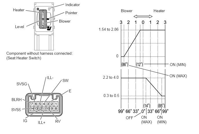
B194050E03
1.01,3.01 1.26,3.677 true 1.115,3.708 0.813,3.573 true 1.094,3.896 0.792,3.927 true 1.438,3.938 0.917,4.25 true 1.594,3.938 1.458,4.302 true 1.76,3.938 2.063,4.281 true 1.438,3.698 1.656,2.771 true 1.604,3.677 2.219,2.875 true 1.771,3.688 2.458,3.26 true 5.271,3.875 5.271,4.125 false 5.813,3.875 5.813,4.125 false 5.083,4.052 4.833,4.208 false 5.188,2.302 6.073,2.302 false 6.073,2.719 4.646,2.354 false 1.75,0.667 2.313,0.448 true 1.563,0.844 2.083,0.74 true 1.802,0.292 2.313,0.146 true 1.51,0.708 0.948,0.948 true 1.521,0.458 0.927,0.375 true 0.417,3.5 0.813,3.646 0.396,0.146 10 false BLRH 0.594,2.938 1.021,3.094 0.427,0.156 10 false SVSG 1.688,2.708 1.969,2.854 0.281,0.146 10 false ILL- 1.365,4.323 1.677,4.479 0.313,0.156 10 false ILL+ 2.25,2.813 2.531,2.958 0.281,0.146 10 false SW 2.479,3.188 2.604,3.344 0.125,0.156 10 false E 1.99,4.281 2.208,4.438 0.219,0.156 10 false RV 0.833,4.26 1,4.417 0.167,0.156 10 false IG 0.406,3.865 0.802,4.01 0.396,0.146 10 false SVS5 4.531,4.156 4.854,4.302 0.323,0.146 10 false OFF 6.115,2.24 6.74,2.427 0.625,0.188 10 false ON (MIN) 6.104,2.646 6.771,2.833 0.667,0.188 10 false ON (MAX) 5.083,4.135 5.49,4.49 0.406,0.354 10 false ON (MAX) 5.656,4.135 6.031,4.49 0.375,0.354 10 false ON (MIN) 3.708,2.698 4.333,2.865 0.625,0.167 10 false 2.2 to 4.0 3.729,3.354 4.344,3.51 0.615,0.156 10 false 0.3 to 0.5 4.354,0.302 4.802,0.479 0.448,0.177 10 false Blower 5.531,0.302 6,0.448 0.469,0.146 10 false Heater 0.229,1.833 2.708,2.177 2.479,0.344 10 false Component without harness connected: (Seat Heater Switch) 3.552,0.969 4.323,1.135 0.771,0.167 10 false 1.54 to 2.86 2.125,0.677 2.573,0.833 0.448,0.156 10 false Blower 0.469,0.271 0.917,0.417 0.448,0.146 10 false Heater 2.354,0.083 2.938,0.229 0.583,0.146 10 false Indicator 2.354,0.375 2.844,0.521 0.49,0.146 10 false Pointer 0.542,0.875 0.917,1.021 0.375,0.146 10 false Level 4.188,1.927 4.323,2.094 0.135,0.167 10 false 0

a.

Check the resistance.

i.

Measure the resistance according to the value(s) in the table below.

Standard Resistance (for Heater):
Tester Connection Switch Condition Specified Condition
4 (SW) - 10 (RV) Switch OFF 2.2 to 4.0 kΩ
Switch ON (Min.)
Switch ON (Max.) 0.3 to 0.5 kΩ


Standard Resistance (for Blower):
Tester Connection Switch Condition Specified Condition
7 (BLRH) - 6 (SVSG) Switch OFF 1.54 to 2.86 kΩ
Switch ON (Min.)
Switch ON (Max.) Below 0.1 kΩ


HINT:

As the dial is being turned, the resistance changes gradually.


If the result is not as specified, replace the switch.


b.

Check the illumination operation.

i.

Apply battery voltage to the switch connector, and check that the seat heater switch illuminates.

OK:
Measurement Condition Switch Condition Specified Condition
Battery positive (+) → 11 (ILL+)
Battery negative (-) → 5 (ILL-)
Always Pointer and level
illuminate


If the result is not as specified, replace the switch.


c.

Check the indicator operation.

i.

Apply battery voltage to the switch connector, and check that the seat heater switch illuminates.

OK:
Measurement Condition Switch Condition Specified Condition
Battery positive (+) → 12 (IG)
Battery negative (-) → 3 (E)
Switch ON Indicator
illuminates


If the result is not as specified, replace the switch.