RM27L0U
_58
Vehicle Interior
_049342
SEAT
_0235879
REAR POWER SEAT CONTROL SYSTEM
J
SEAT REAR POWER SEAT CONTROL SYSTEM Power Source Circuit
DESCRIPTION
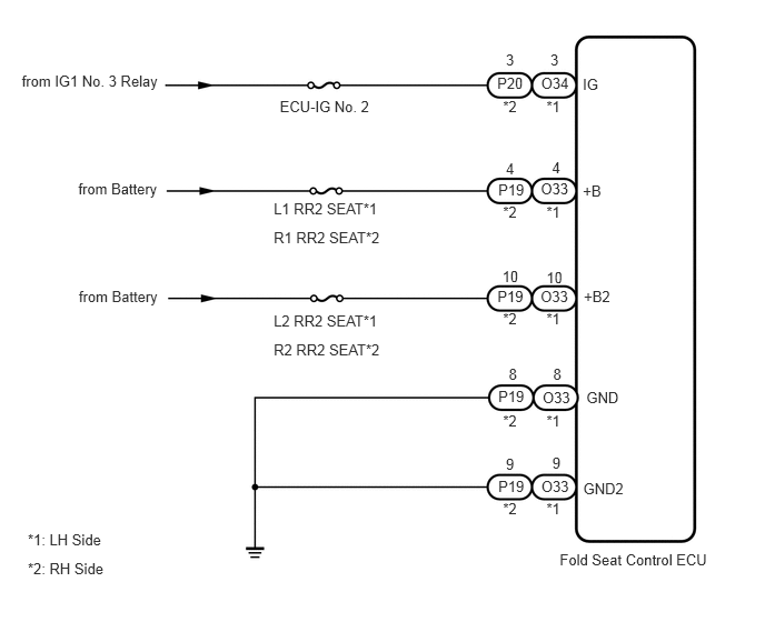
Power is supplied to the fold seat control ECU through the L1 RR2 SEAT*1, L2 RR2 SEAT*1, R1 RR2 SEAT*2 and R2 RR2 SEAT*2 fuses.
*1: LH Side
*2: RH Side
WIRING DIAGRAM
0.204,0.676 1.539,0.858
1.334,0.182
10
from IG1 No. 3 Relay
0.733,1.692 1.570,1.861
0.837,0.170
10
from Battery
0.738,2.697 1.575,2.866
0.837,0.170
10
from Battery
2.621,0.921 3.533,1.072
0.912,0.151
10
ECU-IG No. 2
2.564,1.873 3.659,2.039
1.095,0.165
10
L1 RR2 SEAT*1
2.564,2.15 3.659,2.315
1.095,0.165
10
R1 RR2 SEAT*2
2.564,2.925 3.659,3.090
1.095,0.165
10
L2 RR2 SEAT*1
2.564,3.194 3.659,3.359
1.095,0.165
10
R2 RR2 SEAT*2
4.658,0.696 4.931,0.855
0.274,0.160
10
P20
4.668,1.693 4.942,1.852
0.274,0.160
10
P19
4.66,2.696 4.934,2.856
0.274,0.160
10
P19
4.668,3.638 4.941,3.797
0.274,0.160
10
P19
5.069,0.693 5.388,0.867
0.319,0.174
10
O34
5.066,1.692 5.386,1.866
0.319,0.174
10
O33
5.064,2.699 5.383,2.873
0.319,0.174
10
O33
5.083,3.645 5.402,3.818
0.319,0.174
10
O33
5.071,4.482 5.390,4.656
0.319,0.174
10
O33
4.668,4.484 4.941,4.643
0.274,0.160
10
P19
4.739,0.48 4.841,0.642
0.101,0.162
10
3
5.156,0.48 5.257,0.642
0.101,0.162
10
3
4.739,1.495 4.851,1.675
0.112,0.181
10
4
5.171,1.49 5.283,1.670
0.112,0.181
10
4
4.705,2.507 4.907,2.644
0.202,0.137
10
10
5.119,2.516 5.321,2.653
0.202,0.137
10
10
4.766,3.425 4.873,3.577
0.107,0.152
10
8
5.182,3.432 5.288,3.584
0.107,0.152
10
8
4.739,4.269 4.846,4.436
0.107,0.167
10
9
5.174,4.264 5.281,4.432
0.107,0.167
10
9
5.459,0.705 5.639,0.866
0.179,0.161
10
IG
5.46,1.71 5.653,1.848
0.194,0.139
10
+B
5.469,2.703 5.751,2.864
0.282,0.160
10
+B2
5.493,3.644 5.839,3.797
0.346,0.153
10
GND
5.464,4.496 5.886,4.644
0.423,0.148
10
GND2
5.243,5.163 6.725,5.313
1.482,0.151
10
Fold Seat Control ECU
0.26,4.979 1.047,5.144
0.786,0.165
10
*1: LH Side
0.26,5.247 1.047,5.412
0.786,0.165
10
*2: RH Side
4.712,4.691 5.034,4.886
0.322,0.195
10
*2
5.119,4.691 5.441,4.886
0.322,0.195
10
*1
4.712,3.864 5.034,4.059
0.322,0.195
10
*2
5.119,3.864 5.441,4.059
0.322,0.195
10
*1
4.712,2.911 5.034,3.106
0.322,0.195
10
*2
5.119,2.911 5.441,3.106
0.322,0.195
10
*1
4.712,1.903 5.034,2.098
0.322,0.195
10
*2
5.119,1.903 5.441,2.098
0.322,0.195
10
*1
4.712,0.922 5.034,1.117
0.322,0.195
10
*2
5.119,0.922 5.441,1.117
0.322,0.195
10
*1
PROCEDURE
1.INSPECT FUSE
a.
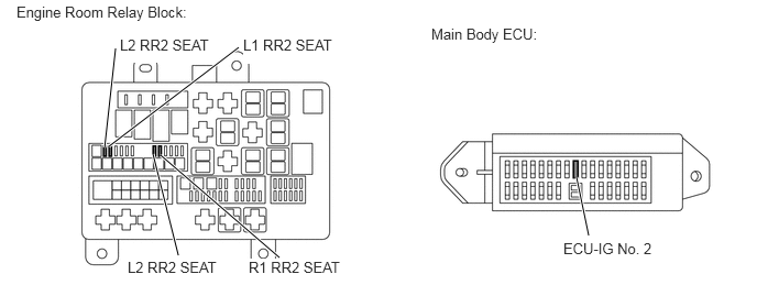
Remove the L1 RR2 SEAT, L2 RR2 SEAT, R1 RR2 SEAT and R2 RR2 SEAT fuses from the engine room relay block.
1.688,2.417 1.448,1.458
true
1.031,1.385 2.26,0.448
true
2.646,2.438 1.521,1.469
true
5.573,2.229 5.458,1.677
true
0.99,1.396 1.094,0.458
true
0.156,0.031 1.833,0.208
1.677,0.177
10
false
Engine Room Relay Block:
2.354,2.448 3.281,2.604
0.927,0.156
10
true
R1 RR2 SEAT
2.302,0.344 3.208,0.604
0.906,0.26
10
true
L1 RR2 SEAT
1.135,0.344 2.01,0.594
0.875,0.25
10
true
L2 RR2 SEAT
1.208,2.448 2.104,2.604
0.896,0.156
10
true
L2 RR2 SEAT
4.083,0.24 5.125,0.417
1.042,0.177
10
false
Main Body ECU:
5.333,2.271 6.26,2.427
0.927,0.156
10
true
ECU-IG No. 2
b.
Remove the ECU-IG No. 2 fuse from the main body ECU.
c.
Measure the resistance according to the value(s) in the table below.
- Standard Resistance:
Tester Connection Condition Specified Condition ECU-IG No. 2 fuse Always Below 1 Ω L1 RR2 SEAT fuse Always Below 1 Ω L2 RR2 SEAT fuse Always Below 1 Ω R1 RR2 SEAT fuse Always Below 1 Ω R2 RR2 SEAT fuse Always Below 1 Ω
OK
2.CHECK HARNESS AND CONNECTOR (POWER SOURCE)
NG
CHECK FOR SHORTS IN ALL HARNESSES AND CONNECTORS CONNECTED TO FUSE AND REPLACE FUSE
2.CHECK HARNESS AND CONNECTOR (POWER SOURCE)
a.
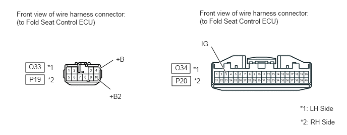
Disconnect the O33 and O34 or P19 and P20 ECU connectors.
0.531,1.302 0.917,1.5
0.385,0.198
0.531,1.552 0.917,1.75
0.385,0.198
3.542,1.323 3.927,1.521
0.385,0.198
3.552,1.583 3.938,1.781
0.385,0.198
2.042,1.438 2.333,1.25
true
2.01,1.635 2.281,1.854
true
4.365,0.969 4.667,1.51
true
0.344,0.208 2.646,0.583
2.302,0.375
10
false
Front view of wire harness connector: (to Fold Seat Control ECU)
0.979,1.313 1.156,1.49
0.177,0.177
10
false
*1
0.99,1.573 1.167,1.75
0.177,0.177
10
false
*2
0.594,1.302 0.865,1.469
0.271,0.167
10
false
O33
0.604,1.563 0.875,1.729
0.271,0.167
10
false
P19
2.396,1.146 2.615,1.323
0.219,0.177
10
false
+B
2.26,1.917 2.542,2.083
0.281,0.167
10
false
+B2
4.125,0.188 6.427,0.563
2.302,0.375
10
false
Front view of wire harness connector:(to Fold Seat Control ECU)
3.615,1.323 3.885,1.49
0.271,0.167
10
false
O34
3.625,1.594 3.896,1.76
0.271,0.167
10
false
P20
3.99,1.354 4.167,1.531
0.177,0.177
10
false
*1
4.01,1.594 4.188,1.771
0.177,0.177
10
false
*2
4.156,0.823 4.354,1
0.198,0.177
10
false
IG
6.198,2.167 6.906,2.354
0.708,0.188
10
false
*1: LH Side
6.208,2.448 6.948,2.635
0.74,0.188
10
false
*2: RH Side
b.
Measure the voltage according to the value(s) in the table below.
- Standard Voltage:
LH Side Tester Connection Condition Specified Condition O33-4 (+B) - Body ground Always 11 to 14 V O33-10 (+B2) - Body ground Always 11 to 14 V O34-3 (IG) - Body ground Ignition switch off Below 1 V Ignition switch ON 11 to 14 V
RH Side Tester Connection Condition Specified Condition P19-4 (+B) - Body ground Always 11 to 14 V P19-10 (+B2) - Body ground Always 11 to 14 V P20-3 (IG) - Body ground Ignition switch off Below 1 V Ignition switch ON 11 to 14 V
OK
3.CHECK HARNESS AND CONNECTOR (GROUND)
NG
REPAIR OR REPLACE HARNESS OR CONNECTOR
3.CHECK HARNESS AND CONNECTOR (GROUND)
a.
0.295,0.254 2.624,0.592
2.328,0.338
10
Front view of wire harness connector: (to Fold Seat Control ECU)
0.082,2.727 0.838,2.878
0.756,0.151
10
*1: LH Side
0.082,3.045 0.838,3.196
0.756,0.151
10
*2: RH Side
0.505,1.743 0.787,1.892
0.281,0.149
10
O33
0.503,2.114 0.784,2.259
0.281,0.145
10
P19
0.924,1.732 1.074,1.899
0.150,0.167
10
*1
0.913,2.115 1.080,2.259
0.167,0.144
10
*2
1.547,2.986 1.913,3.150
0.366,0.164
10
GND
2.242,2.999 2.680,3.151
0.438,0.151
10
GND2
1.802,2.625 1.771,2.986
false
1.95,2.622 2.434,2.999
false
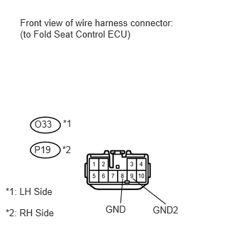
Disconnect the O33 or P19 ECU connector.
b.
Measure the resistance according to the value(s) in the table below.
- Standard Resistance:
LH Side Tester Connection Condition Specified Condition O33-8 (GND) - Body ground Always Below 1 Ω O33-9 (GND2) - Body ground Always Below 1 Ω
RH Side Tester Connection Condition Specified Condition P19-8 (GND) - Body ground Always Below 1 Ω P19-9 (GND2) - Body ground Always Below 1 Ω
OK
PROCEED TO NEXT CIRCUIT INSPECTION SHOWN IN PROBLEM SYMPTOMS TABLE
NG
REPAIR OR REPLACE HARNESS OR CONNECTOR