RM27L0U
_58
Vehicle Interior
_049342
SEAT
_0235879
REAR POWER SEAT CONTROL SYSTEM
J
SEAT REAR POWER SEAT CONTROL SYSTEM Rear Power Seat Switch Circuit
DESCRIPTION
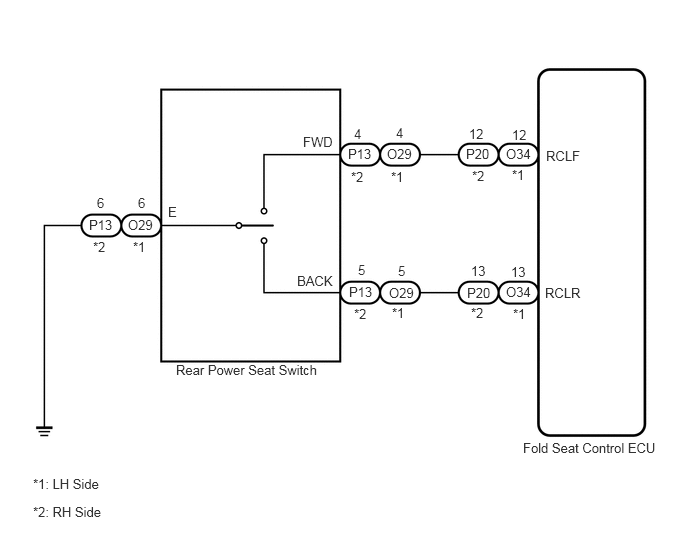
When the rear power seat switch is operated, a recline signal is sent to the fold seat control ECU. The ECU activates the power seat motor based on the signal from the rear power seat switch.
WIRING DIAGRAM
5.448,4.583 6.917,4.74
1.469,0.156
10
false
Fold Seat Control ECU
5.688,1.542 6.135,1.75
0.448,0.208
10
false
RCLF
5.677,2.969 6.146,3.146
0.469,0.177
10
false
RCLR
3.156,1.396 3.5,1.573
0.344,0.177
10
false
FWD
3.094,2.844 3.531,3.031
0.438,0.188
10
false
BACK
1.75,2.125 1.896,2.313
0.146,0.188
10
false
E
5.271,1.521 5.563,1.677
0.292,0.156
10
false
O34
5.271,2.958 5.552,3.115
0.281,0.156
10
false
O34
5.333,1.74 5.51,1.927
0.177,0.188
10
false
*1
5.344,3.188 5.5,3.354
0.156,0.167
10
false
*1
5.333,1.323 5.573,1.521
0.24,0.198
10
false
12
5.323,2.75 5.51,2.917
0.188,0.167
10
false
13
4.854,1.521 5.156,1.677
0.302,0.156
10
false
P20
4.865,2.969 5.146,3.115
0.281,0.146
10
false
P20
4.917,1.75 5.104,1.948
0.188,0.198
10
false
*2
4.906,3.177 5.063,3.344
0.156,0.167
10
false
*2
4.885,1.313 5.125,1.51
0.24,0.198
10
false
12
4.906,2.74 5.083,2.917
0.177,0.177
10
false
13
4.146,2.74 4.26,2.906
0.115,0.167
10
false
5
3.729,2.729 3.854,2.896
0.125,0.167
10
false
5
4.052,2.969 4.313,3.135
0.26,0.167
10
false
O29
4.073,1.76 4.25,1.948
0.177,0.188
10
false
*1
4.083,3.177 4.25,3.354
0.167,0.177
10
false
*1
4.125,1.302 4.25,1.479
0.125,0.177
10
false
4
1.333,2.26 1.594,2.427
0.26,0.167
10
false
O29
1.385,2.49 1.573,2.656
0.188,0.167
10
false
*1
0.927,2.26 1.198,2.427
0.271,0.167
10
false
P13
0.969,2.49 1.156,2.656
0.188,0.167
10
false
*2
1.01,2.031 1.156,2.219
0.146,0.188
10
false
6
1.438,2.031 1.563,2.219
0.125,0.188
10
false
6
3.635,2.958 3.885,3.135
0.25,0.177
10
false
P13
4.031,1.521 4.323,1.698
0.292,0.177
10
false
O29
3.625,1.521 3.875,1.688
0.25,0.167
10
false
P13
3.656,1.76 3.854,1.938
0.198,0.177
10
false
*2
3.688,3.188 3.865,3.365
0.177,0.177
10
false
*2
3.688,1.313 3.813,1.469
0.125,0.156
10
false
4
0.344,4.958 1.146,5.219
0.802,0.26
10
false
*1: LH Side
0.344,5.25 1.177,5.5
0.833,0.25
10
false
*2: RH Side
1.833,3.771 3.417,4.094
1.583,0.323
10
false
Rear Power Seat Switch
PROCEDURE
1.CHECK FOLD SEAT CONTROL ECU (INPUT SIGNAL)
a.
1.198,1.719 1.729,2.198
true
1.135,1.719 0.958,2.198
true
0.094,0.052 2.375,0.646
2.281,0.594
10
false
Component with harness connector: (Fold Seat Control ECU)
1.479,0.969 1.74,1.146
0.26,0.177
10
false
P20
0.74,0.969 1.021,1.146
0.281,0.177
10
false
O34
1.49,2.198 1.927,2.375
0.438,0.177
10
false
RCLF
0.719,2.198 1.125,2.375
0.406,0.177
10
false
RCLR
1.135,0.99 1.302,1.156
0.167,0.167
10
false
*1
1.865,0.979 2.031,1.156
0.167,0.177
10
false
*2
0.083,2.969 0.99,3.156
0.906,0.188
10
false
*2: RH Side
0.083,2.635 0.99,2.823
0.906,0.188
10
false
*1: LH Side
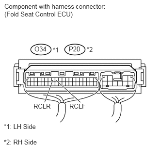
Measure the voltage according to the value(s) in the table below.
- Standard Voltage:
LH side Tester Connection Condition Specified Condition O34-12 (RCLF) - Body ground Always 11 to 14 V Rear power seat switch LH forward Below 1 V O34-13 (RCLR) - Body ground Always 11 to 14 V Rear power seat switch LH backward Below 1 V
RH side Tester Connection Condition Specified Condition P20-12 (RCLF) - Body ground Always 11 to 14 V Rear power seat switch RH forward Below 1 V P20-13 (RCLR) - Body ground Always 11 to 14 V Rear power seat switch RH backward Below 1 V
OK
PROCEED TO NEXT CIRCUIT INSPECTION SHOWN IN PROBLEM SYMPTOMS TABLE
NG
2.INSPECT REAR POWER SEAT SWITCH
2.INSPECT REAR POWER SEAT SWITCH
a.
1.792,3.542 2.198,4.229
true
1.49,3.552 1.229,4.219
true
1.656,3.573 1.656,4.219
true
2.469,0.292 1.865,0.417
false
2.531,1.698 1.979,1.771
false
0.104,2.031 2.51,2.427
2.406,0.396
10
false
Component without harness connected: (Rear Power Seat Switch)
1.417,4.24 1.844,4.427
0.427,0.188
10
false
BACK
2.042,4.24 2.396,4.406
0.354,0.167
10
false
FWD
1.177,4.24 1.333,4.406
0.156,0.167
10
false
E
2.552,1.615 3.115,1.813
0.563,0.198
10
false
Forward
2.51,0.208 3.198,0.406
0.688,0.198
10
false
Backward
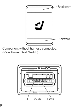
Remove the rear power seat switch (See page Vehicle Interior>SEAT>POWER SEAT SWITCH(for Rear No. 2 Seat)>REMOVAL).
b.
Measure the resistance according to the value(s) in the table below.
- Standard Resistance:
Tester Connection Condition Specified Condition 4 (FWD) - 6 (E) Always 10 kΩ or higher Rear power seat switch forward Below 1 Ω 5 (BACK) - 6 (E) Always 10 kΩ or higher Rear power seat switch backward Below 1 Ω
OK
3.CHECK HARNESS AND CONNECTOR (FOLD SEAT CONTROL ECU - REAR POWER SEAT SWITCH)
NG
REPLACE REAR POWER SEAT SWITCH
3.CHECK HARNESS AND CONNECTOR (FOLD SEAT CONTROL ECU - REAR POWER SEAT SWITCH)
a.
Disconnect the O34 or P20 ECU connector.
0.167,0.99 0.552,1.198
0.385,0.208
0.167,1.26 0.552,1.469
0.385,0.208
3.792,1.167 4.177,1.375
0.385,0.208
3.792,1.438 4.177,1.635
0.385,0.198
4.896,2.292 5.104,1.875
true
5.469,2.292 5.24,1.875
true
1.917,1.906 1.719,1.229
true
2.021,1.917 2.125,1.229
true
0.167,0.125 2.417,0.469
2.25,0.344
10
false
Front view of wire harness connector: (to Fold Seat Control ECU)
4.656,2.313 5.01,2.5
0.354,0.188
10
false
FWD
5.417,2.313 5.844,2.49
0.427,0.177
10
false
BACK
6.375,2.156 7.104,2.333
0.729,0.177
10
false
*1: LH Side
6.375,2.438 7.104,2.615
0.729,0.177
10
false
*2: RH Side
1.479,1.021 1.844,1.188
0.365,0.167
10
false
RCLF
0.208,1.281 0.51,1.469
0.302,0.188
10
false
P20
0.594,1 0.781,1.177
0.188,0.177
10
false
*1
0.604,1.271 0.792,1.448
0.188,0.177
10
false
*2
0.208,1 0.51,1.167
0.302,0.167
10
false
O34
2,1.021 2.365,1.188
0.365,0.167
10
false
RCLR
4.063,0.125 6.313,0.469
2.25,0.344
10
false
Front view of wire harness connector: (to Rear Power Seat Switch)
3.833,1.177 4.135,1.344
0.302,0.167
10
false
O29
3.854,1.448 4.156,1.635
0.302,0.188
10
false
P13
4.219,1.198 4.406,1.375
0.188,0.177
10
false
*1
4.24,1.438 4.427,1.615
0.188,0.177
10
false
*2
b.
Disconnect the O29 or P13 switch connector.
c.
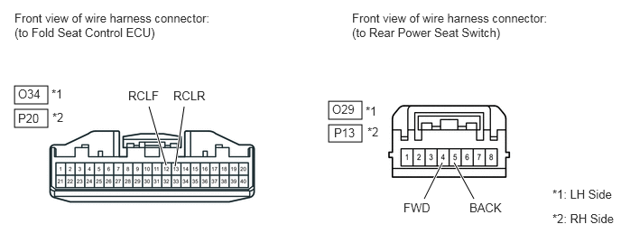
Disconnect the connector from the folding motor.
d.
Measure the resistance according to the value(s) in the table below.
- Standard Resistance:
LH Side Tester Connection Condition Specified Condition O34-12 (RCLF) - O29-4 (FWD) Always Below 1 Ω O34-12 (RCLF) - Body ground Always 10 kΩ or higher O34-13 (RCLR) - O29-5 (BACK) Always Below 1 Ω O34-13 (RCLR) - Body ground Always 10 kΩ or higher
RH Side Tester Connection Condition Specified Condition P20-12 (RCLF) - P13-4 (FWD) Always Below 1 Ω P20-12 (RCLF) - Body ground Always 10 kΩ or higher P20-13 (RCLR) - P13-5 (BACK) Always Below 1 Ω P20-13 (RCLR) - Body ground Always 10 kΩ or higher
OK
REPAIR OR REPLACE HARNESS OR CONNECTOR (REAR POWER SEAT SWITCH - BODY GROUND)
NG
REPAIR OR REPLACE HARNESS OR CONNECTOR