Home › Vehicle Interior › SEAT › POWER SEAT SWITCH(for Rear No. 2 Seat)
RM27L0U _58 Vehicle Interior _049342 SEAT _0235881 POWER SEAT SWITCH(for Rear No. 2 Seat) G

SEAT  POWER SEAT SWITCH(for Rear No. 2 Seat)  INSPECTION  


PROCEDURE

Hide 84923 1.INSPECT REAR POWER SEAT SWITCH
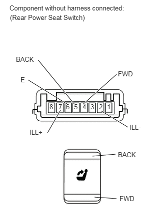
E159000E04
1.729,2.177 2.427,1.552 true 1.552,2.177 0.792,1.25 true 2.104,2.313 2.667,2.656 true 1.26,2.302 0.99,2.771 true 1.406,2.177 0.583,1.667 true 1.927,3.26 2.406,3.219 false 1.969,4.115 2.427,4.146 false 0.198,0.083 2.677,0.24 2.479,0.156 10 false Component without harness connected: 2.229,2.146 2.344,2.313 0.115,0.167 10 false 1 2.063,2.146 2.167,2.302 0.104,0.156 10 false 2 1.885,2.146 1.99,2.292 0.104,0.146 10 false 3 1.719,2.146 1.823,2.281 0.104,0.135 10 false 4 1.542,2.146 1.646,2.292 0.104,0.146 10 false 5 1.375,2.146 1.479,2.302 0.104,0.156 10 false 6 2.458,1.458 2.802,1.604 0.344,0.146 10 false FWD 0.333,1.156 0.75,1.313 0.417,0.156 10 false BACK 0.615,2.677 0.969,2.844 0.354,0.167 10 false ILL+ 2.698,2.573 2.99,2.74 0.292,0.167 10 false ILL- 0.427,1.583 0.552,1.729 0.125,0.146 10 false E 2.49,4.063 2.833,4.208 0.344,0.146 10 false FWD 2.458,3.146 2.875,3.302 0.417,0.156 10 false BACK 1.219,2.146 1.323,2.302 0.104,0.156 10 false 7 1.031,2.146 1.135,2.302 0.104,0.156 10 false 8 0.208,0.281 1.854,0.469 1.646,0.188 10 false (Rear Power Seat Switch)

a.

Measure the resistance according to the value(s) in the table below.

Standard Resistance:
Tester Connection Switch Condition Specified Condition
5 (BACK) - 6 (E) BACK Below 1 Ω
5 (BACK) - 6 (E) OFF 10 kΩ or higher
4 (FWD) - 6 (E) FWD Below 1 Ω
4 (FWD) - 6 (E) OFF 10 kΩ or higher


If the result is not as specified, replace the switch.


b.

Apply battery voltage to the switch connector, and check that the rear power seat switch illuminates.

OK:
Measurement Condition Condition Specified Condition
Battery positive (+) → 7 (ILL+)
Battery negative (-) → 2 (ILL-)
Always Illuminates


If the result is not as specified, replace the switch.


Hide 84190 2.INSPECT FOLD SEAT SWITCH ASSEMBLY (for RH Side)
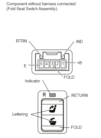
E158999E06
2.01,3.448 2.365,3.25 false 2.031,4.323 2.375,4.323 false 2.198,2.125 2.573,2.125 true 1.979,2.094 2.521,1.406 true 1.802,2.229 2.125,2.583 true 1.573,2.094 0.979,1.385 true 1.365,2.208 0.969,2.208 true 1.698,3.167 1.448,2.719 false 1.698,3.729 1.052,3.875 1.052,3.875 1.698,4.083 false 2.104,2.073 2.24,2.25 0.135,0.177 10 false 1 1.917,2.073 2.052,2.25 0.135,0.177 10 false 2 1.74,2.073 1.875,2.25 0.135,0.177 10 false 3 1.552,2.073 1.646,2.271 0.094,0.198 10 false 4 1.365,2.073 1.5,2.229 0.135,0.156 10 false 5 0.219,0.042 2.74,0.406 2.521,0.365 10 false Component without harness connected: (Fold Seat Switch Assembly) 2.417,4.229 2.844,4.406 0.427,0.177 10 false FOLD 2.427,3.146 3.083,3.323 0.656,0.177 10 false RETURN 2.167,2.531 2.594,2.708 0.427,0.177 10 false FOLD 0.542,1.302 0.958,1.479 0.417,0.177 10 false RTRN 0.813,2.146 0.948,2.323 0.135,0.177 10 false E 2.615,2.042 2.813,2.188 0.198,0.146 10 false +B 2.583,1.323 2.854,1.49 0.271,0.167 10 false IND 0.844,2.656 1.427,2.823 0.583,0.167 10 false Indicator 0.417,3.781 0.99,3.969 0.573,0.188 10 false Lettering

a.

Measure the resistance according to the value(s) in the table below.

Standard Resistance:
Tester Connection Switch Condition Specified Condition
3 (FOLD) - 5 (E) FOLD Below 1 Ω
3 (FOLD) - 5 (E) OFF 10 kΩ or higher
4 (RTRN) - 5 (E) RETURN Below 1 Ω
4 (RTRN) - 5 (E) OFF 10 kΩ or higher


If the result is not as specified, replace the switch.


b.

Apply battery voltage to the switch connector, and check that the fold seat switch assembly illuminates.

OK:
Measurement Condition Condition Specified Condition
Battery positive (+) → 2 (IND)
Battery negative (-) → 5 (E)
Always Indicator illuminates
Battery positive (+) → 1 (+B)
Battery negative (-) → 5 (E)
Always Lettering illuminates


If the result is not as specified, replace the switch.


Hide 84190 3.INSPECT FOLD SEAT SWITCH ASSEMBLY (for LH Side)
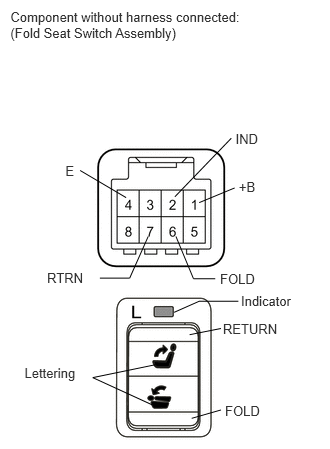
B386412E02
0.108,0.09 2.628,0.475 2.520,0.385 10 Component without harness connected: (Fold Seat Switch Assembly) 2.344,4.197 2.766,4.355 0.422,0.158 10 FOLD 2.322,3.348 2.938,3.506 0.615,0.158 10 RETURN 2.292,2.823 2.714,2.980 0.422,0.158 10 FOLD 0.49,2.811 0.911,2.969 0.421,0.158 10 RTRN 0.681,1.702 0.812,1.854 0.131,0.152 10 E 2.487,1.863 2.716,2.009 0.228,0.146 10 +B 2.453,1.366 2.716,1.524 0.263,0.158 10 IND 0.834,1.775 1.313,2.058 false 2.074,2.11 2.444,1.957 false 1.821,2.049 2.409,1.439 false 1.974,3.486 2.301,3.421 false 1.996,4.357 2.301,4.27 false 2.51,3.05 3.096,3.220 0.586,0.170 10 Indicator 0.255,3.802 0.847,3.984 0.592,0.182 10 Lettering 1.641,3.794 0.966,3.933 0.966,3.933 1.59,4.219 false 1.04,2.897 1.35,2.897 1.35,2.897 1.543,2.463 false 2.242,2.903 2.015,2.903 2.015,2.903 1.832,2.462 false 2.483,3.138 2.073,3.138 2.073,3.138 1.813,3.253 false

a.

Measure the resistance according to the value(s) in the table below.

Standard Resistance:
Tester Connection Switch Condition Specified Condition
6 (FOLD) - 4(E) FOLD Below 1 Ω
6 (FOLD) - 4(E) OFF 10 kΩ or higher
7 (RTRN) - 4(E) RETURN Below 1 Ω
7 (RTRN) - 4(E) OFF 10 kΩ or higher


If the result is not as specified, replace the switch.


b.

Apply battery voltage to the switch connector, and check that the fold seat switch assembly illuminates.

OK:
Measurement Condition Condition Specified Condition
Battery positive (+) → 2 (IND)
Battery negative (-) → 4(E)
Always Indicator illuminates
Battery positive (+) → 1 (+B)
Battery negative (-) → 4(E)
Always Lettering illuminates


If the result is not as specified, replace the switch.


Hide 84190 4.INSPECT FOLD SEAT SWITCH ASSEMBLY (for Luggage Compartment RH Seat)
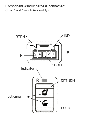
E158999E07
2.042,3.458 2.396,3.229 false 2.052,4.313 2.396,4.313 false 2.188,2.125 2.563,2.125 false 1.969,2.083 2.51,1.396 true 1.792,2.229 2.115,2.583 false 1.563,2.083 1.052,1.458 true 1.365,2.208 0.979,2.208 false 1.698,3.177 1.448,2.729 false 1.677,3.76 1.052,3.875 1.052,3.875 1.698,4.083 false 2.104,2.073 2.24,2.25 0.135,0.177 10 false 1 1.917,2.073 2.052,2.25 0.135,0.177 10 false 2 1.74,2.073 1.875,2.25 0.135,0.177 10 false 3 1.552,2.073 1.646,2.271 0.094,0.198 10 false 4 1.365,2.083 1.5,2.24 0.135,0.156 10 false 5 0.219,0.156 2.74,0.521 2.521,0.365 10 false Component without harness connected: (Fold Seat Switch Assembly) 2.438,4.229 2.865,4.406 0.427,0.177 10 false FOLD 2.427,3.146 3.083,3.323 0.656,0.177 10 false RETURN 2.167,2.521 2.594,2.698 0.427,0.177 10 false FOLD 0.625,1.385 1.021,1.563 0.396,0.177 10 false RTRN 0.802,2.135 0.938,2.313 0.135,0.177 10 false E 2.594,2.021 2.792,2.167 0.198,0.146 10 false +B 2.552,1.344 2.823,1.51 0.271,0.167 10 false IND 0.844,2.646 1.385,2.813 0.542,0.167 10 false Indicator 0.302,3.771 0.875,3.958 0.573,0.188 10 false Lettering

a.

Measure the resistance according to the value(s) in the table below.

Standard Resistance:
Tester Connection Switch Condition Specified Condition
3 (FOLD) - 5 (E) FOLD Below 1 Ω
3 (FOLD) - 5 (E) OFF 10 kΩ or higher
4 (RTRN) - 5 (E) RETURN Below 1 Ω
4 (RTRN) - 5 (E) OFF 10 kΩ or higher


If the result is not as specified, replace the switch.


b.

Apply battery voltage to the switch connector, and check that the fold seat switch assembly illuminates.

OK:
Measurement Condition Condition Specified Condition
Battery positive (+) → 2 (IND)
Battery negative (-) → 5 (E)
Always Indicator illuminates
Battery positive (+) → 1 (+B)
Battery negative (-) → 5 (E)
Always Lettering illuminates


If the result is not as specified, replace the switch.


Hide 84190 5.INSPECT FOLD SEAT SWITCH ASSEMBLY (for Luggage Compartment LH Seat)

B386412E02
0.108,0.09 2.628,0.475 2.520,0.385 10 Component without harness connected: (Fold Seat Switch Assembly) 2.344,4.197 2.766,4.355 0.422,0.158 10 FOLD 2.322,3.348 2.938,3.506 0.615,0.158 10 RETURN 2.292,2.823 2.714,2.980 0.422,0.158 10 FOLD 0.49,2.811 0.911,2.969 0.421,0.158 10 RTRN 0.681,1.702 0.812,1.854 0.131,0.152 10 E 2.487,1.863 2.716,2.009 0.228,0.146 10 +B 2.453,1.366 2.716,1.524 0.263,0.158 10 IND 0.834,1.775 1.313,2.058 false 2.074,2.11 2.444,1.957 false 1.821,2.049 2.409,1.439 false 1.974,3.486 2.301,3.421 false 1.996,4.357 2.301,4.27 false 2.51,3.05 3.096,3.220 0.586,0.170 10 Indicator 0.255,3.802 0.847,3.984 0.592,0.182 10 Lettering 1.641,3.794 0.966,3.933 0.966,3.933 1.59,4.219 false 1.04,2.897 1.35,2.897 1.35,2.897 1.543,2.463 false 2.242,2.903 2.015,2.903 2.015,2.903 1.832,2.462 false 2.483,3.138 2.073,3.138 2.073,3.138 1.813,3.253 false

a.

Measure the resistance according to the value(s) in the table below.

Standard Resistance:
Tester Connection Switch Condition Specified Condition
6 (FOLD) - 4(E) FOLD Below 1 Ω
6 (FOLD) - 4(E) OFF 10 kΩ or higher
7 (RTRN) - 4(E) RETURN Below 1 Ω
7 (RTRN) - 4(E) OFF 10 kΩ or higher


If the result is not as specified, replace the switch.


b.

Apply battery voltage to the switch connector, and check that the fold seat switch assembly illuminates.

OK:
Measurement Condition Condition Specified Condition
Battery positive (+) → 2 (IND)
Battery negative (-) → 4(E)
Always Indicator illuminates
Battery positive (+) → 1 (+B)
Battery negative (-) → 4(E)
Always Lettering illuminates


If the result is not as specified, replace the switch.