HEATING / AIR CONDITIONING REFRIGERANT ON-VEHICLE INSPECTION
PROCEDURE

 1. CHECK REFRIGERANT PRESSURE USING MANIFOLD GAUGE SET
This is a method to identify trouble areas by using a manifold gauge set. Read the manifold gauge pressure under the following conditions.
Test conditions:
Engine warm.
All doors fully open.
A/C switch ON.
Blower speed control switch at HI.
Engine running at 1500 rpm.
Air inlet mode damper set at RECIRC.
Temperature control lever in MAX. COLD position.
Air temperature at air inlet 30 to 35°C (86 to 95°F).
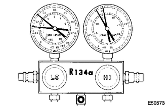
When the refrigerant volume is correct, the gauge reading indicates as follows:
- Gauge Reading:
Pressure Side Refrigerant Volume Low 147 to 245 kPa (1.5 to 2.5 kgf/cm2, 21 to 36 psi) High 1373 to 1569 kPa (14 to 16 kgf/cm2, 199 to 228 psi)
- HINT:
-
Pressure varies in accordance with certain conditions (outside air temperature, sunlight and wind).
When there is moisture in the refrigeration system:
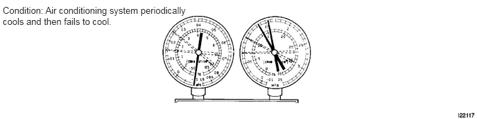
| Symptom | Probable Cause | Diagnosis | Corrective Action |
|---|---|---|---|
| During operation, pressure on low pressure side cycles between normal and vacuum. | Moisture in refrigeration system freezes at expansion valve orifice, causing temporary interruption of cycle.
However, when melted, returns to normal condition. |
·
Receiver dryer oversaturated. ·
Moisture in refrigeration system freezes at expansion valve orifice and blocks refrigerant circulation. |
1.
Replace receiver dryer. 2.
Remove moisture from cycle by repeatedly evacuating air. 3.
Supply appropriate volume of new refrigerant. |
When cooling is insufficient:
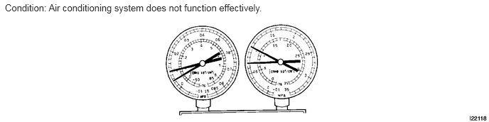
| Symptom | Probable Cause | Diagnosis | Corrective Action |
|---|---|---|---|
·
Pressure low on both low and high pressure sides. ·
Cooling performance insufficient. |
Gas leakage from refrigeration system. | ·
Insufficient refrigerant. ·
Refrigerant leakage. |
1.
Check for gas leakage using gas leak detector, and repair if necessary. 2.
Supply appropriate volume of new refrigerant. 3.
If indicated pressure value close to 0 when connected to gauge, create vacuum after inspecting and repairing location of leakage. |
When the circulation of the refrigerant is poor:
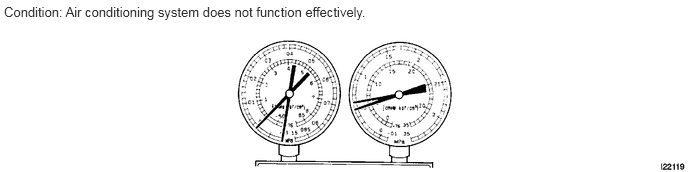
| Symptom | Probable Cause | Diagnosis | Corrective Action |
|---|---|---|---|
·
Pressure low on both low and high pressure sides. ·
Frost exists on piping from condenser to A/C unit. |
Refrigerant flow obstructed by dirt in condenser. | Condenser clogged. | Replace condenser. |
When the refrigerant does not circulate:
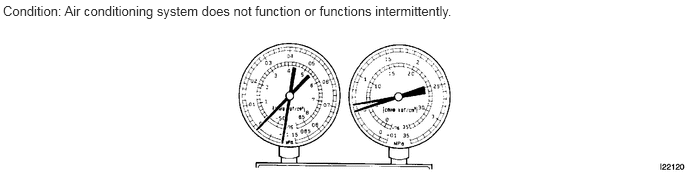
| Symptom | Probable Cause | Diagnosis | Corrective Action |
|---|---|---|---|
·
Vacuum indicated on low pressure side, and extremely low pressure indicated on high pressure side. ·
Frost or condensation seen on piping on both sides of condenser or expansion valve. |
·
Refrigerant flow obstructed by moisture or dirt in refrigeration system. ·
Refrigerant flow obstructed by gas leakage from expansion valve. |
Refrigerant does not circulate. | 1.
Check expansion valve. 2.
Clean expansion valve with compressed air. 3.
Replace condenser. 4.
Evacuate air and then supply appropriate volume of new refrigerant. 5.
For gas leakage from expansion valve, replace expansion valve. |
When the refrigerant is overcharged or cooling of condenser is insufficient:
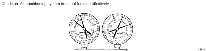
| Symptom | Probable Cause | Diagnosis | Corrective Action |
|---|---|---|---|
·
Pressure extremely high on both sides. |
·
Excessive refrigerant. ·
Cooling performance of condenser insufficient. |
·
Excessive refrigerant. ·
Cooling performance of condenser insufficient. |
1.
Clean condenser fins. 2.
Check condenser fan motor operation by switching A/C ON. 3.
If 1 and 2 normal, check amount of refrigerant and supply appropriate volume of refrigerant. |
When there is air in the refrigeration system:
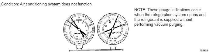
| Symptom | Probable Cause | Diagnosis | Corrective Action |
|---|---|---|---|
·
Pressure extremely high on both low and high pressure sides. ·
Low pressure piping too hot to touch. |
Air in refrigeration system. | ·
Air in refrigeration system. ·
Insufficient vacuum purging. |
1.
Check whether compressor oil dirty or insufficient. 2.
Evacuate air and supply new refrigerant. |
When the expansion valve malfunctions:
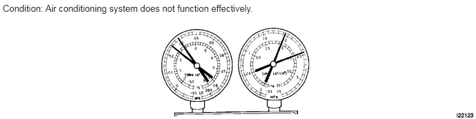
| Symptom | Probable Cause | Diagnosis | Corrective Action |
|---|---|---|---|
·
Pressure extremely high on both low and high pressure sides. ·
Frost or condensation on piping on low pressure side. |
Expansion valve malfunction. | ·
Excessive refrigerant in low pressure piping. ·
Expansion valve opening too wide. |
Replace expansion valve. |
When the compressor is defective:
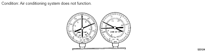
| Symptom | Probable Cause | Diagnosis | Corrective Action |
|---|---|---|---|
·
Pressure extremely high on both low and high pressure sides. ·
Pressure extremely low on high pressure side. |
Internal leakage in compressor. | ·
Compression failure of compressor. ·
Leakage from damaged valve or broken sliding parts in compressor. |
Repair or replace compressor. |
2.INSPECT IDLING SPEED
Warm up the engine.
Inspect idling speed when these conditions are established.
- HINT:
- ·
Blower speed control switch at Hi.
·Temperature control switch in MAX. COLD position.
·Shift lever in N.
- Standard:
Condition Idling Speed Magnetic clutch not engaged
(Switch A/C OFF)650 to 750 rpm Magnetic clutch engaged
(Switch A/C ON)750 to 850 rpm
If the idling speed is not as specified, check the idle control system.