RM27L0U
_58
Vehicle Interior
_049344
HEATING / AIR CONDITIONING
_0235913
SOLAR SENSOR
G
HEATING / AIR CONDITIONING SOLAR SENSOR INSPECTION
PROCEDURE

 89120
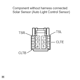
1.INSPECT SOLAR SENSOR (AUTOMATIC LIGHT CONTROL SENSOR)
1.917,1.604 2.385,1.375
true
1.906,1.813 2.365,1.813
true
1.167,2.271 1.594,2.01
true
1.094,1.427 1.573,1.625
true
0.542,0.26 3.021,0.896
2.479,0.635
10
false
Component without harness connected: Solar Sensor (Auto Light Control Sensor)
0.802,1.323 1.26,1.521
0.458,0.198
10
false
TSR
0.792,2.188 1.25,2.385
0.458,0.198
10
false
CLTB
2.406,1.281 2.865,1.479
0.458,0.198
10
false
TSL
2.406,1.719 2.865,1.917
0.458,0.198
10
false
CLTE
a.
Remove the solar sensor with the connector still connected.
b.
Apply battery voltage between terminals 6 (CLTB) and 3 (CLTE) of the A/C solar sensor.
c.
Measure the voltage according to the value(s) in the table below.
- Standard Voltage:
Tester Connection Condition Specified Condition 1 (TSL) - 3 (CLTE) Sensor subject to electric light 0.8 to 4.3 V 1 (TSL) - 3 (CLTE) Sensor covered with a cloth Below 0.8 V 2 (TSR) - 3 (CLTE) Sensor subject to electric light 0.8 to 4.3 V 2 (TSR) - 3 (CLTE) Sensor covered with a cloth Below 0.8 V
If the result is not as specified, replace the solar sensor.
- HINT:
- ·
As the inspection light is moved away from the sensor, the voltage increases.
·Use an incandescent lamp for inspection. Bring it within 30 cm (11.8 in.) of the solar sensor.