RM27L0U
_59
Vehicle Exterior
_049347
WINDOW / GLASS
_0235942
POWER WINDOW MASTER SWITCH
G
WINDOW / GLASS POWER WINDOW MASTER SWITCH INSPECTION
PROCEDURE

 84820
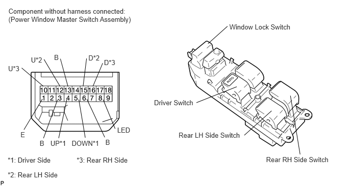
1.INSPECT POWER WINDOW MASTER SWITCH
a.
Check the resistance.
0.172,0.142 2.807,0.507
2.635,0.365
10
Component without harness connected: (Power Window Master Switch Assembly)
4.683,0.465 6.041,0.659
1.358,0.194
10
Window Lock Switch
3.146,2.023 3.994,2.203
0.847,0.180
10
Driver Switch
3.647,2.688 4.978,2.882
1.331,0.194
10
Rear LH Side Switch
5.433,3.192 6.795,3.374
1.362,0.182
10
Rear RH Side Switch
4.246,0.895 4.644,0.538
false
4.01,2.104 4.834,1.777
false
4.987,2.772 5.545,2.271
false
6.127,3.164 5.929,1.961
false
2.152,2.834 2.263,2.975
0.111,0.141
10
B
0.419,2.678 0.531,2.847
0.112,0.169
10
E
0.81,2.854 0.936,3.003
0.126,0.149
10
B
1.03,2.856 1.384,3.017
0.354,0.161
10
UP*1
2.124,1.197 2.374,1.351
0.250,0.154
10
D*3
1.805,1.108 2.066,1.259
0.260,0.151
10
D*2
0.632,1.144 0.883,1.294
0.251,0.150
10
U*2
1.105,1.092 1.226,1.237
0.121,0.145
10
B
0.167,1.321 0.419,1.462
0.251,0.141
10
U*3
0.158,3.195 1.170,3.364
1.012,0.169
10
*1: Driver Side
0.158,3.496 1.299,3.646
1.141,0.150
10
*2: Rear LH Side
1.565,3.195 2.652,3.361
1.087,0.166
10
*3: Rear RH Side
1.896,1.77 2.097,1.293
false
0.884,1.768 0.442,1.392
false
2.091,2.497 2.299,2.429
false
1.773,2.032 2.138,2.814
false
1.175,2.043 0.887,2.833
false
0.865,2.029 0.488,2.658
false
1.227,1.772 0.898,1.217
false
1.232,1.204 1.388,1.774
false
1.696,1.766 1.767,1.197
false
2.394,2.584 2.689,2.740
0.295,0.156
10
LED
1.464,2.855 2.079,3.011
0.614,0.156
10
DOWN*1
1.362,2.042 1.198,2.831
false
1.74,2.822 1.608,2.038
false
2.105,2.042 2.35,2.638
false
i.
Measure the resistance according to the value(s) in the table below.
- HINT:
-
Window motors other than the driver MANUAL and rear seat window motors use LIN communication, and therefore this inspection cannot be performed for those windows.
- Standard Resistance:
Driver Switch Tester Connection Window Lock Switch Condition Power Window Switch Condition Specified Condition 1 (E) - 4 (UP)
5 (DOWN) - 13 (B)Always
(ON/OFF)UP Below 1 Ω 4 (UP) - 13 (B)
5 (DOWN) - 13 (B)Always
(ON/OFF)OFF Below 1 Ω 1 (E) - 5 (DOWN)
4 (UP) - 13 (B)Always
(ON/OFF)DOWN MANUAL Below 1 Ω
If the result is not as specified, replace the power window master switch.
- Standard Resistance:
Rear LH Side Switch Tester Connection Window Lock Switch Condition Power Window Switch Condition Specified Condition 13 (B) - 12 (U)
1 (E) - 15 (D)OFF UP Below 1 Ω 1 (E) - 12 (U)
1 (E) - 15 (D)OFF OFF Below 1 Ω 13 (B) - 15 (D)
1 (E) - 12 (U)OFF DOWN Below 1 Ω 13 (B) - 12 (U) ON UP Below 1 Ω 1 (E) - 15 (D) ON UP 10 kΩ or higher 12 (U) - 15 (D) ON OFF Below 1 Ω 13 (B) - 15 (D) ON DOWN Below 1 Ω 1 (E) - 12 (U) ON DOWN 10 kΩ or higher
If the result is not as specified, replace the power window master switch.
- Standard Resistance:
Rear RH Side Switch Tester Connection Window Lock Switch Condition Power Window Switch Condition Specified Condition 13 (B) - 10 (U)
1 (E) - 16 (D)OFF UP Below 1 Ω 1 (E) - 10 (U)
1 (E) - 16 (D)OFF OFF Below 1 Ω 13 (B) - 16 (D)
1 (E) - 10 (U)OFF DOWN Below 1 Ω 13 (B) - 10 (U) ON UP Below 1 Ω 1 (E) - 16 (D) ON UP 10 kΩ or higher 10 (U) - 16 (D) ON OFF Below 1 Ω 13 (B) - 16 (D) ON DOWN Below 1 Ω 1 (E) - 10 (U) ON DOWN 10 kΩ or higher
If the result is not as specified, replace the power window master switch.
b.
Check the illumination operation.
i.
Apply battery voltage to the power window master switch and check that the illumination comes on.
- OK:
Measurement Condition Specified Condition Battery positive (+) → Terminal 8 (LED)
Battery negative (-) → Terminal 1 (E)Illumination comes on
If the result is not as specified, replace the power window master switch.