RM27L0U
_59
Vehicle Exterior
_049349
DOOR / HATCH
_0235968
POWER BACK DOOR SYSTEM
U
DOOR / HATCH POWER BACK DOOR SYSTEM TERMINALS OF ECU
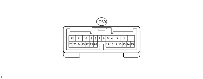
CHECK POWER BACK DOOR DRIVE UNIT (POWER BACK DOOR ECU)
3.479,0.688 3.771,0.833
0.292,0.146
10
false
O30
a.
Disconnect the O30 ECU connector.
b.
Measure the voltage and resistance according to the value(s) in the table below:
| Terminal No. (Symbol) | Wiring Color | Terminal Description | Condition | Specified Condition |
|---|---|---|---|---|
| O30-10 (ECUB) - Body ground | R - Body ground | ECUB power supply | Always | 11 to 14 V |
| O30-12 (B) - Body ground | L - Body ground | B power supply | Always | 11 to 14 V |
| O30-8 (IG) - Body ground | GR - Body ground | IG power supply | Ignition switch ON | 11 to 14 V |
| O30-8 (IG) - Body ground | GR - Body ground | IG power supply | Ignition switch off | Below 1 V |
| O30-20 (FUL) - Body ground | R - Body ground | Back door courtesy light switch signal circuit | Back door is opened | Below 1 Ω |
| O30-20 (FUL) - Body ground | R - Body ground | Back door courtesy light switch signal circuit | Back door is closed | 10 kΩ or higher |
| O30-4 (DS1) - Body ground | SB - Body ground | Back door closer switch signal circuit | Back door closer switch ON | Below 1 Ω |
| O30-4 (DS1) - Body ground | SB - Body ground | Back door closer switch signal circuit | Back door closer switch OFF | 10 kΩ or higher |
| O30-15 (OSL) - O30-14 (OSE) | LG - Y | Power back door touch sensor LH circuit | Back door touch sensor LH not pressed | 950 to 1050 Ω |
| O30-15 (OSL) - O30-14 (OSE) | LG - Y | Power back door touch sensor LH circuit | Back door touch sensor LH pressed | Below 100 Ω |
| O30-13 (OSR) - O30-14 (OSE) | BR - Y | Power back door touch sensor RH circuit | Back door touch sensor RH not pressed | 950 to 1050 Ω |
| O30-13 (OSR) - O30-14 (OSE) | BR - Y | Power back door touch sensor RH circuit | Back door touch sensor RH pressed | Below 100 Ω |
| O30-11 (GND) - Body ground | W-B - Body ground | Ground | Always | Below 1 Ω |
If the result is not as specified, there may be a malfunction on the wire harness side.
c.
Reconnect the O30 ECU connector.
d.
Measure the voltage according to the value(s) in the table below:
| Terminal No. (Symbol) | Wiring Color | Terminal Description | Condition | Specified Condition |
|---|---|---|---|---|
| O30-26 (BZR+) - Body ground | P - Body ground | Power back door warning buzzer signal input | Back door warning buzzer is sounding | 11 to 14 V |
| O30-26 (BZR+) - Body ground | P - Body ground | Power back door warning buzzer signal input | Back door warning buzzer is stopped | Below 1 V |
| O30-2 (DC+) - O30-1 (DC-) | P - SB | Power back door lock motor circuit | Back door lock motor is operating | 11 to 14 V |
| O30-2 (DC+) - O30-1 (DC-) | P - SB | Power back door lock motor circuit | Back door lock motor is stopped | Below 1 V |
| O30-22 (HAF) - Body ground | V - Body ground | Back door lock half-latch switch signal circuit | Back door is opened →
Back door closer motor is operating → Back door is closed |
Below 1 V →
11 to 14 V → Below 1 V |
| O30-24 (POS) - Body ground | BE - Body ground | Back door lock position switch signal circuit | Back door is opened →
Back door closer motor is operating → Back door is closed |
Below 1 V →
11 to 14 V → Below 1 V |
- HINT:
-
If the result is not as specified, the ECU may have a malfunction.
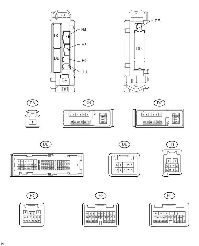
CHECK MAIN BODY ECU (COWL SIDE JUNCTION BLOCK LH)
2.875,1.073 2.792,1.073
2.792,1.073 2.375,1.333
false
5.521,0.75 5.427,0.75
5.427,0.75 5.021,1
true
2.875,1.604 2.802,1.604
2.802,1.604 2.396,1.76
false
2.948,2.594 2.865,2.594
2.865,2.594 2.448,2.344
false
2.896,2.219 2.823,2.219
2.823,2.219 2.417,2.115
false
2.219,2.802 2.448,2.969
0.229,0.167
10
false
DA
1.948,2.021 2.156,2.188
0.208,0.167
10
false
DB
1.948,1.198 2.156,1.365
0.208,0.167
10
false
DC
4.906,1.667 5.125,1.833
0.219,0.167
10
false
DD
5.573,0.667 5.781,0.833
0.208,0.167
10
false
DE
2.979,2.51 3.198,2.677
0.219,0.167
10
false
H1
2.948,2.104 3.167,2.271
0.219,0.167
10
false
H2
2.938,1.531 3.156,1.698
0.219,0.167
10
false
H3
2.927,0.99 3.146,1.156
0.219,0.167
10
false
H4
3.083,3.615 3.292,3.771
0.208,0.156
10
false
DB
1.552,5.115 1.771,5.26
0.219,0.146
10
false
DD
4.396,5.115 4.604,5.26
0.208,0.146
10
false
DE
1.073,3.625 1.281,3.771
0.208,0.146
10
false
DA
5.656,3.625 5.885,3.771
0.229,0.146
10
false
DC
6.01,6.969 6.208,7.125
0.198,0.156
10
false
H4
3.552,6.969 3.75,7.115
0.198,0.146
10
false
H3
1.073,6.979 1.281,7.125
0.208,0.146
10
false
H2
6.104,5.125 6.302,5.26
0.198,0.135
10
false
H1
a.
Disconnect the DD and H4 connectors.
b.
Measure the resistance according to the value(s) in the table below.
| Terminal No. (Symbol) | Wiring Color | Terminal Description | Condition | Specified Condition |
|---|---|---|---|---|
| H4-26 (PBDS) - Body ground | R - Body ground | Power back door open/close switch signal circuit | Power back door open/close switch ON | Below 1 Ω |
| H4-26 (PBDS) - Body ground | R - Body ground | Power back door open/close switch signal circuit | Power back door open/close switch OFF | 10 kΩ or higher |
| DD-62 (GND1,GND2) - Body ground | W-B - Body ground | Ground | Always | Below 1 Ω |
If the result is not as specified, there may be a malfunction on the wire harness side.