Home › Vehicle Exterior › WIPER / WASHER › WIPER AND WASHER SYSTEM
RM27L0U _59 Vehicle Exterior _049351 WIPER / WASHER _0235977 WIPER AND WASHER SYSTEM J

WIPER / WASHER  WIPER AND WASHER SYSTEM  Headlight Cleaner Switch Circuit  


DESCRIPTION

This circuit detects the conditions of the headlight cleaner switch.

·

Headlight cleaner switch signal

·

Headlight operating signal


WIRING DIAGRAM
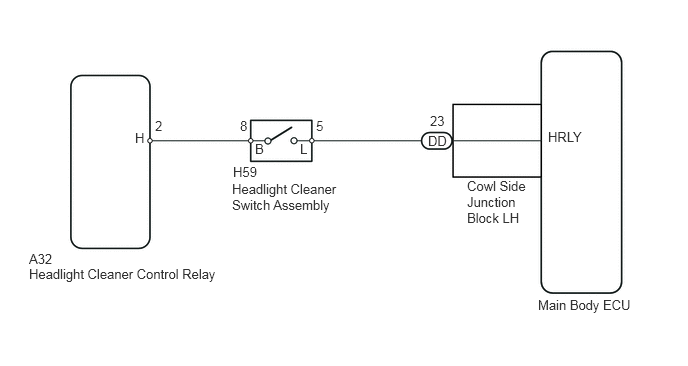
E162509E02
3.292,1.229 3.385,1.375 0.094,0.146 10 false 5 3.125,1.469 3.25,1.635 0.125,0.167 10 false L 2.656,1.469 2.781,1.615 0.125,0.146 10 false B 2.5,1.229 2.604,1.375 0.104,0.146 10 false 8 5.604,3.094 6.604,3.271 1,0.177 10 false Main Body ECU 4.479,1.177 4.646,1.323 0.167,0.146 10 false 23 5.708,1.344 6.104,1.5 0.396,0.156 10 false HRLY 0.302,2.771 2.344,2.948 2.042,0.177 10 false Headlight Cleaner Control Relay 1.615,1.229 1.708,1.375 0.094,0.146 10 false 2 1.406,1.354 1.531,1.5 0.125,0.146 10 false H 2.427,1.708 2.729,1.865 0.302,0.156 10 false H59 2.417,1.885 3.552,2.208 1.135,0.323 10 false Headlight Cleaner Switch Assembly 4.458,1.385 4.677,1.542 0.219,0.156 10 false DD 0.302,2.615 0.573,2.76 0.271,0.146 10 false A32 4.865,1.854 5.552,2.354 0.688,0.5 10 false Cowl Side Junction Block LH

PROCEDURE

1.CHECK HEADLIGHT ASSEMBLY (LO BEAM)
a.

Check that the headlights illuminate in LO beam.

OK:

Headlights illuminate in LO beam


OK

2.INSPECT HEADLIGHT CLEANER SWITCH ASSEMBLY

NG

2.INSPECT HEADLIGHT CLEANER SWITCH ASSEMBLY
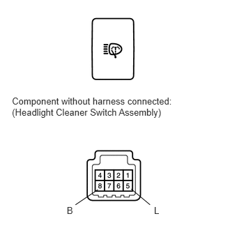
a.
E157699E03
0.998,3.06 1.145,3.197 0.147,0.137 10 B 2.302,3.06 2.473,3.197 0.171,0.137 10 L 1.462,2.834 1.127,3.06 false 1.961,2.825 2.242,3.06 false 0.179,1.427 2.679,1.845 2.500,0.419 10 Component without harness connected: (Headlight Cleaner Switch Assembly)

Remove the headlight cleaner switch assembly.


b.

Measure the resistance according to the value(s) in the table below.

Standard Resistance:
Tester Connection Switch Condition Specified Condition
5 (L) - 8 (B) Headlight cleaner switch OFF 10 kΩ or higher
Headlight cleaner switch ON Below 1 Ω


c.

Reinstall the headlight cleaner switch assembly.


OK

3.CHECK HARNESS AND CONNECTOR (HEADLIGHT CLEANER SWITCH ASSEMBLY - HEADLIGHT CLEANER CONTROL RELAY AND MAIN BODY ECU)

NG

REPLACE HEADLIGHT CLEANER SWITCH ASSEMBLY

3.CHECK HARNESS AND CONNECTOR (HEADLIGHT CLEANER SWITCH ASSEMBLY - HEADLIGHT CLEANER CONTROL RELAY AND MAIN BODY ECU)
a.

Disconnect the A32 headlight cleaner control relay connector.
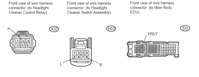
E344988E01
0.792,1.427 0.396,1.073 false 2.667,2.115 2.26,2.281 false 3.156,2.115 3.542,2.302 false 5.094,1.729 5.281,1.271 false 0.313,0.031 1.875,0.552 1.563,0.521 10 false Front view of wire harness connector: (to Headlight Cleaner Control Relay) 2.417,0.031 4.031,0.552 1.615,0.521 10 false Front view of wire harness connector: (to Headlight Cleaner Switch Assembly) 4.688,0.021 6.281,0.552 1.594,0.531 10 false Front view of wire harness connector: (to Main Body ECU) 1.833,0.969 2.292,1.167 0.458,0.198 10 false A32 3.885,0.958 4.344,1.156 0.458,0.198 10 false H59 6.573,0.948 6.885,1.146 0.313,0.198 10 false DD 0.271,0.958 0.427,1.156 0.156,0.198 10 false H 2.156,2.24 2.313,2.438 0.156,0.198 10 false L 3.583,2.271 3.74,2.469 0.156,0.198 10 false B 5.323,1.146 5.938,1.344 0.615,0.198 10 false HRLY


b.

Disconnect the H59 headlight cleaner switch assembly connector.


c.

Disconnect the DD main body ECU connector.


d.

Measure the resistance according to the value(s) in the table below.

Standard Resistance:
Tester Connection Condition Specified Condition
A32-2 (H) - H59-8 (B) Always Below 1 Ω
A32-2 (H) or H59-8 (B) - Body ground Always 10 kΩ or higher
H59-5 (L) - DD-23 (HRLY) Always Below 1 Ω
H59-5 (L) or DD-23 (HRLY) - Body ground Always 10 kΩ or higher


e.

Reconnect the headlight cleaner control relay connector.


f.

Reconnect the headlight cleaner switch assembly connector.


g.

Reconnect the main body ECU connector.


OK

REPLACE HEADLIGHT CLEANER CONTROL RELAY

NG

REPAIR OR REPLACE HARNESS OR CONNECTOR