Home › Vehicle Exterior › WIPER / WASHER › WIPER AND WASHER SYSTEM
RM27L0U _59 Vehicle Exterior _049351 WIPER / WASHER _0235977 WIPER AND WASHER SYSTEM J

WIPER / WASHER  WIPER AND WASHER SYSTEM  Headlight Cleaner Motor and Relay Circuit  


DESCRIPTION

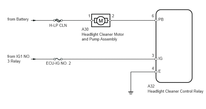
This circuit provides power to the headlight cleaner control relay.

The headlight cleaner control relay sends the signal from the switch, etc. to the headlight cleaner motor to operate the headlight cleaner system.

WIRING DIAGRAM
E162516E02
5.137,3.106 7.152,3.285 2.015,0.180 10 Headlight Cleaner Control Relay 5.509,0.598 5.728,0.743 0.219,0.144 10 PB 5.509,1.957 5.719,2.104 0.210,0.147 10 IG 5.509,2.406 5.725,2.576 0.216,0.170 10 E 5.28,0.468 5.496,0.638 0.216,0.170 10 6 5.28,1.85 5.496,2.020 0.216,0.170 10 3 5.28,2.298 5.496,2.468 0.216,0.170 10 4 3.066,0.468 3.278,0.638 0.211,0.170 10 1 3.895,0.468 4.107,0.638 0.211,0.170 10 2 0.259,0.58 1.059,0.769 0.799,0.188 10 from Battery 0.256,1.887 1.065,2.364 0.809,0.477 10 from IG1 NO. 3 Relay 1.715,0.798 2.365,0.980 0.650,0.181 10 H-LP CLN 1.6,2.124 2.617,2.305 1.016,0.181 10 ECU-IG NO. 2 2.842,1.116 4.407,1.444 1.566,0.328 10 Headlight Cleaner Motor and Pump Assembly 2.842,0.934 3.108,1.109 0.266,0.175 10 A30 5.137,2.93 5.449,3.083 0.312,0.153 10 A32

PROCEDURE

1.INSPECT FUSE (ECU-IG No. 2, H-LP CLN)
a.

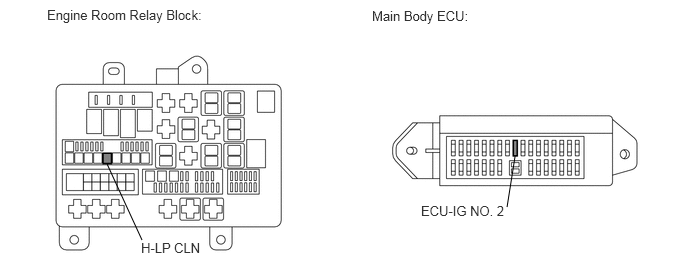
Remove the ECU-IG No. 2 fuse from the main body ECU.
E344990E01
1.115,1.708 1.479,2.5 false 5.365,1.625 5.281,2.156 false 0.49,0.073 4.156,0.271 3.667,0.198 10 false Engine Room Relay Block: 3.875,0.083 6.021,0.281 2.146,0.198 10 false Main Body ECU: 1.469,2.5 2.698,2.698 1.229,0.198 10 false H-LP CLN 4.385,2.115 6.208,2.313 1.823,0.198 10 false ECU-IG NO. 2


b.

Remove the H-LP CLN fuse from the engine junction block.


c.

Measure the resistance according to the value(s) in the table below.

Standard Resistance:
Tester Connection Condition Specified Condition
ECU-IG No. 2 fuse Always Below 1 Ω
H-LP CLN fuse


d.

Reinstall the ECU-IG No. 2 fuse.


e.

Reinstall the H-LP CLN fuse.


OK

2.CHECK HARNESS AND CONNECTOR (HEADLIGHT CLEANER CONTROL RELAY - BATTERY AND BODY GROUND)

NG

REPLACE FUSE

2.CHECK HARNESS AND CONNECTOR (HEADLIGHT CLEANER CONTROL RELAY - BATTERY AND BODY GROUND)
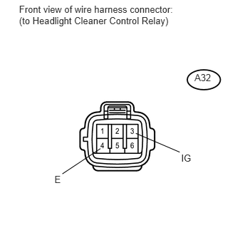
a.
U154112E01
0.279,0.048 2.636,0.426 2.357,0.378 10 Front view of wire harness connector: (to Headlight Cleaner Control Relay) 2.845,1.049 3.109,1.231 0.264,0.181 10 A32 0.797,2.543 0.907,2.704 0.110,0.161 10 E 2.65,2.225 2.839,2.372 0.188,0.147 10 IG 0.912,2.543 1.469,2.173 false 2.628,2.225 1.986,1.95 false

Disconnect the A32 headlight cleaner control relay connector.


b.

Measure the voltage according to the value(s) in the table below.

Standard Voltage:
Tester Connection Switch Condition Specified Condition
A32-3 (IG) - Body ground Ignition switch off Below 1 V
Ignition switch ON 11 to 14 V


c.

Measure the resistance according to the value(s) in the table below.

Standard Resistance:
Tester Connection Condition Specified Condition
A32-4 (E) - Body ground Always Below 1 Ω


d.

Reconnect the headlight cleaner control relay connector.


OK

3.INSPECT HEADLIGHT CLEANER MOTOR AND PUMP ASSEMBLY

NG

REPAIR OR REPLACE HARNESS OR CONNECTOR

3.INSPECT HEADLIGHT CLEANER MOTOR AND PUMP ASSEMBLY
a.

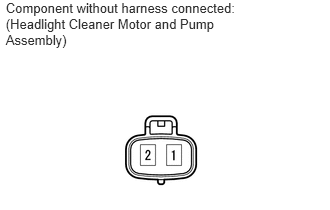
Remove the A30 headlight cleaner motor and pump assembly.

B172829E03
0.06,0 2.567,0.592 2.507,0.592 10 Component without harness connected: (Headlight Cleaner Motor and Pump Assembly)

b.

Connect the battery positive (+) lead to terminal 1 and the negative (-) lead to terminal 2.


c.

Check that the rear washer motor operates.

OK:

Headlight cleaner motor operates.


d.

Remove the headlight cleaner motor and pump assembly.


OK

4.CHECK HARNESS AND CONNECTOR (CLEANER MOTOR - HEADLIGHT CLEANER CONTROL RELAY AND BATTERY)

NG

REPLACE HEADLIGHT CLEANER MOTOR AND PUMP ASSEMBLY

4.CHECK HARNESS AND CONNECTOR (CLEANER MOTOR - HEADLIGHT CLEANER CONTROL RELAY AND BATTERY)
a.
U153932E01
2.275,4.365 2.500,4.523 0.225,0.158 10 PB 1.988,3.849 2.353,4.322 false 0.179,0 2.590,0.524 2.411,0.524 10 Front view of wire harness connector: (to Headlight Cleaner Motor and Pump Assembly) 0.196,2.25 2.521,2.598 2.325,0.348 10 Front view of wire harness connector: (to Headlight Cleaner Control Relay) 2.668,1.086 2.932,1.267 0.264,0.181 10 A30 2.711,3.202 2.975,3.383 0.264,0.181 10 A32

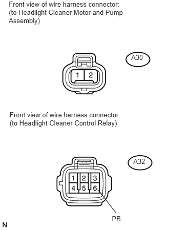
Disconnect the A30 headlight cleaner motor and pump connector.


b.

Disconnect the A32 headlight cleaner control relay connector.


c.

Measure the voltage according to the value(s) in the table below.

Standard Voltage:
Tester Connection Condition Specified Condition
A30-1 - Body ground Always 11 to 14 V


d.

Measure the resistance according to the value(s) in the table below.

Standard Resistance:
Tester Connection Condition Specified Condition
A30-2 - A32-6 (PB) Always Below 1 Ω
A30-2 or A32-6 (PB) - Body ground Always 10 kΩ or higher


e.

Reconnect the headlight cleaner motor and pump connector.


f.

Reconnect the headlight cleaner control relay connector.


OK

PROCEED TO NEXT CIRCUIT INSPECTION SHOWN IN PROBLEM SYMPTOMS TABLE

NG

REPAIR OR REPLACE HARNESS OR CONNECTOR