Home › Vehicle Exterior › WIPER / WASHER › WIPER AND WASHER SYSTEM
RM27L0U _59 Vehicle Exterior _049351 WIPER / WASHER _0235977 WIPER AND WASHER SYSTEM J

WIPER / WASHER  WIPER AND WASHER SYSTEM  Washer Motor Circuit  


DESCRIPTION

·

The main body ECU controls the rear washer motor.

·

Perform this inspection with the back door window glass fully closed.


WIRING DIAGRAM
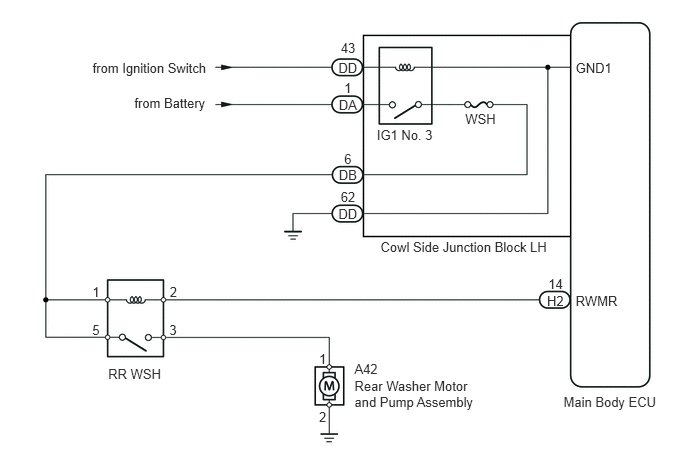
E160108E01
0.964,0.621 2.197,0.770 1.232,0.149 10 from Ignition Switch 3.692,3.937 5.010,4.271 1.318,0.334 10 Rear Washer Motor and Pump Assembly 5.87,4.104 6.933,4.256 1.062,0.152 10 Main Body ECU 1.127,3.811 1.733,3.974 0.606,0.163 10 RR WSH 3.585,1.568 3.690,1.714 0.105,0.145 10 6 5.711,2.873 5.888,3.019 0.177,0.145 10 14 5.996,3.057 6.465,3.212 0.468,0.156 10 RWMR 3.529,1.742 3.746,1.881 0.217,0.139 10 DB 4.846,1.161 5.195,1.301 0.349,0.141 10 WSH 0.962,2.963 1.059,3.112 0.097,0.149 10 1 1.768,2.963 1.864,3.102 0.097,0.139 10 2 1.764,3.359 1.868,3.510 0.104,0.151 10 3 0.961,3.359 1.061,3.515 0.100,0.156 10 5 3.963,2.494 5.785,2.668 1.823,0.174 10 Cowl Side Junction Block LH 3.692,3.758 3.962,3.897 0.270,0.139 10 A42 3.323,3.66 3.423,3.823 0.100,0.163 10 1 3.323,4.263 3.420,4.408 0.097,0.145 10 2 5.698,3.054 5.900,3.210 0.202,0.156 10 H2 1.399,0.992 2.200,1.148 0.802,0.156 10 from Battery 3.925,1.324 4.550,1.480 0.625,0.156 10 IG1 No. 3 3.585,0.838 3.690,0.984 0.105,0.145 10 1 3.529,1.012 3.746,1.151 0.217,0.139 10 DA 3.55,0.421 3.725,0.567 0.174,0.145 10 43 3.525,0.62 3.749,0.758 0.224,0.139 10 DD 5.996,0.63 6.400,0.770 0.404,0.140 10 GND1 3.525,2.151 3.749,2.289 0.224,0.139 10 DD 3.549,1.973 3.726,2.110 0.177,0.137 10 62

PROCEDURE

1.PERFORM ACTIVE TEST USING TECHSTREAM (REAR WIPER WASHER)
a.

Connect the Techstream to the DLC3.


b.

Turn the ignition switch to ON.


c.

Turn the Techstream on.


d.

Enter the following menus: Body Electrical / Main Body / Active Test.


e.

According to the display on the Techstream, perform the Active Test.


Main Body
Tester Display Test Part Control Range Diagnostic Note
Rear Wiper Washer Motor Relay Rear Wiper Washer motor operation ON/OFF -

OK:

Rear washer motor operates.


OK

PROCEED TO NEXT CIRCUIT INSPECTION SHOWN IN PROBLEM SYMPTOMS TABLE

NG

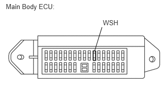
2.INSPECT FUSE (WSH)
a.
B188612E07
1.92,1.052 1.973,1.25 0.053,0.198 0.12,0.048 1.267,0.251 1.147,0.202 10 Main Body ECU: 2.117,0.382 2.465,0.528 0.348,0.147 10 WSH 2.099,0.561 1.947,1.052 false

Remove the WSH fuse from the main body ECU.


b.

Measure the resistance according to the value(s) in the table below.

Standard Resistance:
Tester Connection Condition Specified Condition
WSH fuse Always Below 1 Ω


c.

Reinstall the WSH fuse.


OK

3.CHECK HARNESS AND CONNECTOR (BATTERY - REAR WASHER MOTOR)

NG

REPLACE FUSE

3.CHECK HARNESS AND CONNECTOR (BATTERY - REAR WASHER MOTOR)
a.
U154109E02
0.302,0 2.635,0.49 2.333,0.49 10 false Front view of wire harness connector: (to Rear Washer Motor and Pump Assembly) 2.635,1.125 2.896,1.302 0.26,0.177 10 false A42

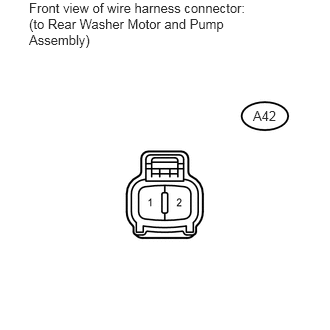
Disconnect the A42 rear washer motor and pump assembly connector.


b.

Measure the voltage according to the value(s) in the table below.

Standard Voltage:
Tester Connection Switch Condition Specified Condition
A42-1 - Body ground Ignition switch ON and rear washer switch OFF Below 1 V
Ignition switch ON and rear washer switch ON 11 to 14 V


c.

Reconnect the rear washer motor and pump assembly connector.


OK

4.INSPECT REAR WASHER MOTOR AND PUMP ASSEMBLY

NG

5.INSPECT RR WSH RELAY
4.INSPECT REAR WASHER MOTOR AND PUMP ASSEMBLY
a.

Remove the rear washer motor and pump assembly.
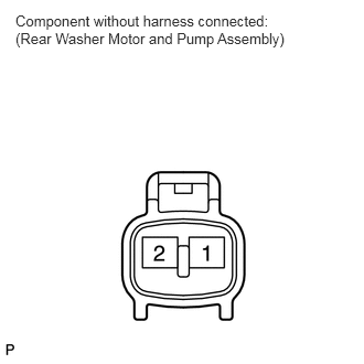

E344991E01
0.146,0.115 2.74,0.563 2.594,0.448 10 false Component without harness connected: (Rear Washer Motor and Pump Assembly)

b.

Connect the battery positive (+) lead to terminal 1 and the negative (-) lead to terminal 2.


c.

Check that the rear washer motor operates.

OK:

Rear washer motor operates.


d.

Reinstall the rear washer motor and pump assembly.


OK

REPAIR OR REPLACE HARNESS AND CONNECTOR (REAR WASHER MOTOR - BODY GROUND)

NG

REPLACE REAR WASHER MOTOR AND PUMP ASSEMBLY

5.INSPECT RR WSH RELAY
a.
E121182E07
3.245,1.033 3.356,1.182 0.111,0.149 10 5 1.703,0.064 1.813,0.213 0.111,0.149 10 2 3.168,0.064 3.279,0.213 0.111,0.149 10 1 3.245,1.651 3.356,1.800 0.111,0.149 10 3 1.374,1.424 1.485,1.573 0.111,0.149 10 3 1.374,0.874 1.485,1.023 0.111,0.149 10 2 0.306,0.874 0.417,1.023 0.111,0.149 10 1 0.306,1.424 0.417,1.573 0.111,0.149 10 5 2.14,0.528 1.857,0.225 false 2.788,0.539 3.168,0.242 false 3.229,1.124 2.677,1.078 false 3.245,1.726 2.677,1.574 false

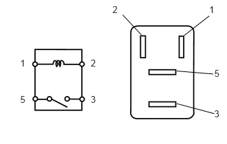
Remove the RR WSH relay from the engine room relay block.

b.

Measure the resistance according to the value(s) in the table below.

Standard Resistance:
Tester Connection Condition Specified Condition
3 - 5 When battery voltage is not applied to terminals 1 and 2 10 kΩ or higher
When battery voltage is applied to terminals 1 and 2 Below 1 Ω


c.

Reinstall the RR WSH relay.


OK

6.CHECK HARNESS AND CONNECTOR (RR WSH RELAY - BATTERY)

NG

REPLACE RR WSH RELAY

6.CHECK HARNESS AND CONNECTOR (RR WSH RELAY - BATTERY)
a.

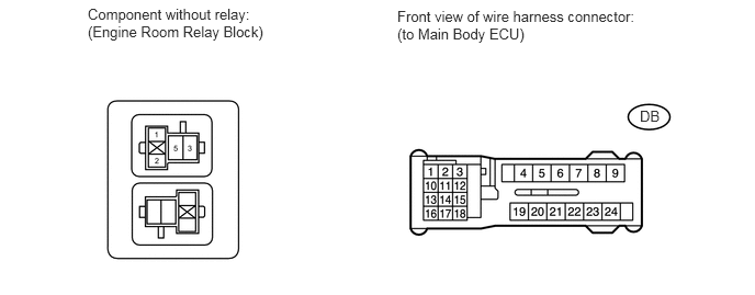
Remove the RR WSH relay from the engine room relay block.
E344992E01
0.833,0.052 2.542,0.417 1.708,0.365 10 false Component without relay: (Engine Room Relay Block) 3.771,0.073 6.01,0.438 2.24,0.365 10 false Front view of wire harness connector: (to Main Body ECU) 6.073,1.021 6.385,1.219 0.313,0.198 10 false DB


b.

Disconnect the DB main body ECU connector.


c.

Measure the resistance according to the value(s) in the table below.

Standard Resistance:
Tester Connection Condition Specified Condition
Terminals 1 - DB-6 Always Below 1 Ω
Terminals 1 or DB-6 - Body ground Always 10 kΩ or higher
Terminals 5 - DB-6 Always Below 1 Ω
Terminals 5 - Body ground Always 10 kΩ or higher


d.

Reinstall the RR WSH relay.


OK

7.CHECK HARNESS AND CONNECTOR (RR WSH RELAY - REAR WASHER MOTOR)

NG

REPAIR OR REPLACE HARNESS OR CONNECTOR

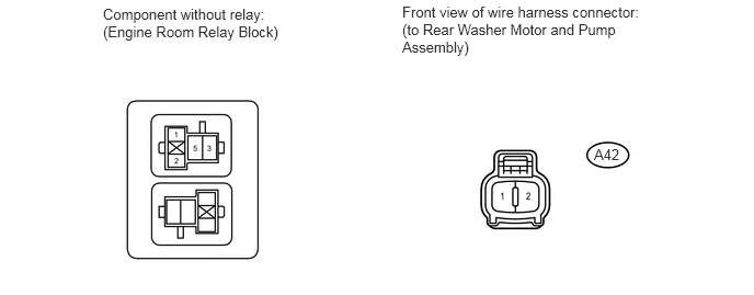
7.CHECK HARNESS AND CONNECTOR (RR WSH RELAY - REAR WASHER MOTOR)
a.

Remove the RR WSH relay from the engine room relay block.
E344993E01
0.979,0.052 2.656,0.406 1.677,0.354 10 false Component without relay: (Engine Room Relay Block) 3.823,0.031 6.24,0.583 2.417,0.552 10 false Front view of wire harness connector: (to Rear Washer Motor and Pump Assembly) 5.646,1.385 6.104,1.583 0.458,0.198 10 false A42


b.

Disconnect the A42 rear washer motor and pump assembly connector.


c.

Measure the resistance according to the value(s) in the table below.

Standard Resistance:
Tester Connection Condition Specified Condition
Terminals 3 - A42-1 Always Below 1 Ω
Terminals 3 or A42-1 - Body ground Always 10 kΩ or higher


d.

Reinstall the RR WSH relay.


e.

Reconnect the rear washer motor and pump assembly connector.


OK

8.CHECK HARNESS AND CONNECTOR (RR WSH RELAY - MAIN BODY ECU)

NG

REPAIR OR REPLACE HARNESS OR CONNECTOR

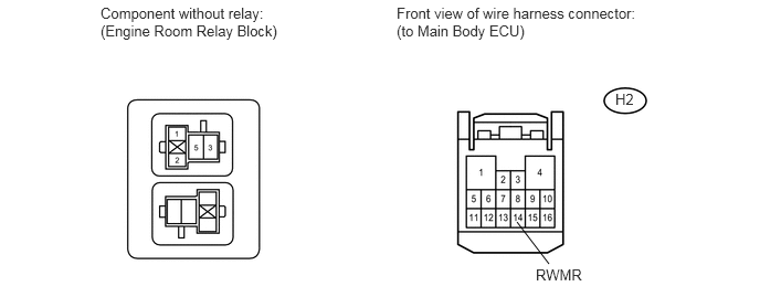
8.CHECK HARNESS AND CONNECTOR (RR WSH RELAY - MAIN BODY ECU)
a.

Remove the RR WSH relay from the engine room relay block.

E344994E01
4.875,2.094 5.177,2.49 false 0.948,0.042 2.667,0.438 1.719,0.396 10 false Component without relay: (Engine Room Relay Block) 3.74,0.042 6.01,0.427 2.271,0.385 10 false Front view of wire harness connector: (to Main Body ECU) 5.802,0.854 6.115,1.052 0.313,0.198 10 false H2 5.052,2.51 5.667,2.708 0.615,0.198 10 false RWMR


b.

Disconnect the H2 main body ECU connector.


c.

Measure the resistance according to the value(s) in the table below.

Standard Resistance:
Tester Connection Condition Specified Condition
Terminals 2 - H2-14 (RWMR) Always Below 1 Ω
Terminals 2 or H2-14 (RWMR) - Body ground Always 10 kΩ or higher


d.

Reinstall the RR WSH relay.


e.

Reconnect the main body ECU connector.


OK

9.CHECK HARNESS AND CONNECTOR (REAR WASHER MOTOR - BODY GROUND)

NG

REPAIR OR REPLACE HARNESS OR CONNECTOR

9.CHECK HARNESS AND CONNECTOR (REAR WASHER MOTOR - BODY GROUND)
a.
U154109E02
0.302,0 2.635,0.49 2.333,0.49 10 false Front view of wire harness connector: (to Rear Washer Motor and Pump Assembly) 2.635,1.125 2.896,1.302 0.26,0.177 10 false A42

Disconnect the A42 rear washer motor and pump assembly connector.


b.

Measure the resistance according to the value(s) in the table below.

Standard Resistance:
Tester Connection Condition Specified Condition
A42-2 - Body ground Always Below 1 Ω


c.

Reconnect the rear washer motor and pump assembly connector.


OK

10.CHECK HARNESS AND CONNECTOR (BATTERY - MAIN BODY ECU)

NG

REPAIR OR REPLACE HARNESS OR CONNECTOR

10.CHECK HARNESS AND CONNECTOR (BATTERY - MAIN BODY ECU)
a.
U154011E02
0.156,0.042 2.542,0.396 2.385,0.354 10 false Front view of wire harness connector: (to Main Body ECU) 2.698,1.24 2.906,1.385 0.208,0.146 10 false DA

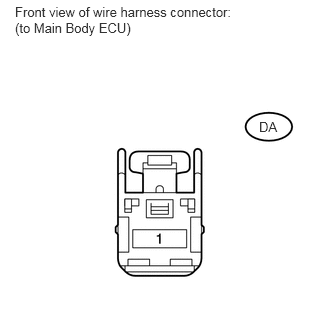
Disconnect the DA main body ECU connector.


b.

Measure the voltage according to the value(s) in the table below.

Standard Voltage:
Tester Connection Condition Specified Condition
DA-1 - Body ground Always 11 to 14 V


c.

Reconnect the main body ECU connector.


OK

11.CHECK HARNESS AND CONNECTOR (MAIN BODY ECU - IGNITION SWITCH, BODY GROUND)

NG

REPAIR OR REPLACE HARNESS OR CONNECTOR

11.CHECK HARNESS AND CONNECTOR (MAIN BODY ECU - IGNITION SWITCH, BODY GROUND)
a.
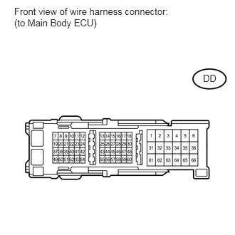
U154115E02
0.208,0.083 2.573,0.417 2.365,0.333 10 false Front view of wire harness connector: (to Main Body ECU) 2.969,1.063 3.188,1.24 0.219,0.177 10 false DD

Disconnect the DD main body ECU connector.


b.

Measure the voltage according to the value(s) in the table below.

Standard Voltage:
Tester Connection Switch Condition Specified Condition
DD-43 - Body ground Ignition switch off Below 1 V
Ignition switch ON 11 to 14 V


c.

Measure the resistance according to the value(s) in the table below.

Standard Resistance:
Tester Connection Condition Specified Condition
DD-62 - Body ground Always Below 1 Ω


d.

Reconnect the main body ECU connector.


OK

REPLACE MAIN BODY ECU

NG

REPAIR OR REPLACE HARNESS OR CONNECTOR