LIGHTING (EXT) LIGHTING SYSTEM TERMINALS OF ECU
CHECK MAIN BODY ECU
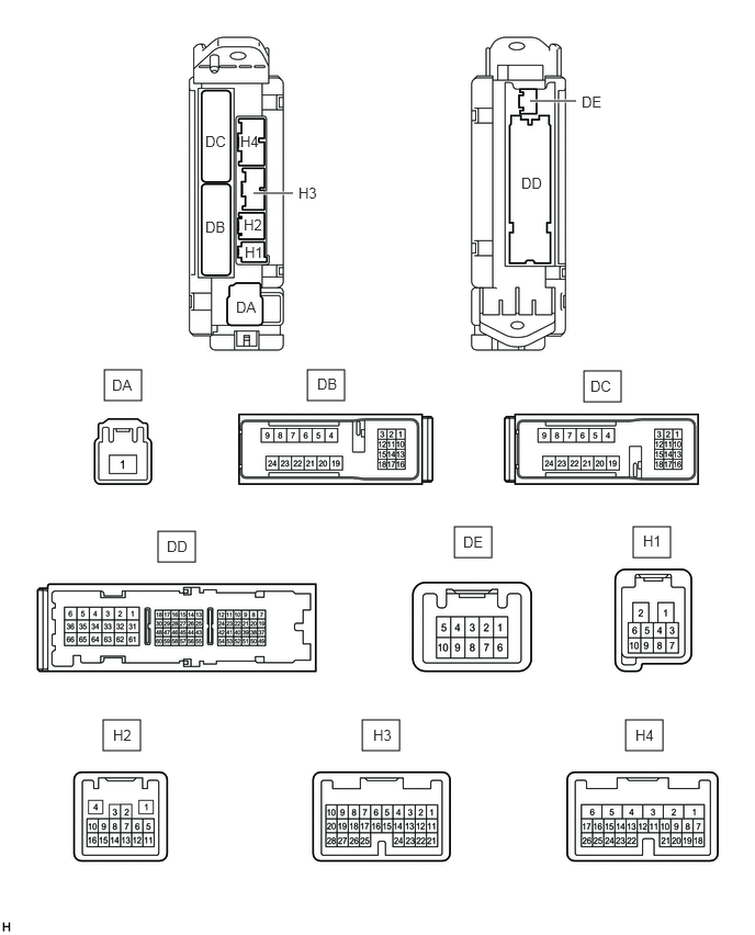
Disconnect the DD, H2, H3 and H4 main body ECU connectors.
Measure the resistance according to the value(s) in the table below.
| Terminal No. (Symbol) | Wiring Color | Terminal Description | Condition | Specified Condition |
|---|---|---|---|---|
| DD-62 (GND1, GND2) - Body ground | W-B - Body ground | Body ground | Always | Below 1 Ω |
| H2-4 (HAZ) - Body ground | BE - Body ground | Hazard warning signal switch input signal | Hazard warning signal switch OFF → ON | 10 kΩ or higher → Below 1 Ω |
| H3-28 (FFOG) - Body ground | P - Body ground | Front fog light switch signal | Front fog light switch OFF → ON | 10 kΩ or higher → Below 1 Ω |
| H3-17 (HEAD) - Body ground | W - Body ground | Light control switch HEAD signal | Light control switch HEAD | Below 1 Ω |
| Light control switch except HEAD | 10 kΩ or higher | |||
| H3-21 (PCTY) - Body ground | BE - Body ground | Front door courtesy light switch RH signal | Front door RH open → closed | Below 1 Ω → 10 kΩ or higher |
| H4-21 (A) - Body ground | G - Body ground | Light control switch AUTO signal | Light control switch AUTO | Below 1 Ω |
| Light control switch except AUTO | 10 kΩ or higher | |||
| H4-23 (TAIL) - Body ground | BE - Body ground | Light control switch TAIL signal | Light control switch TAIL | Below 1 Ω |
| Light control switch except TAIL | 10 kΩ or higher | |||
| H4-24 (DCTY) - Body ground | BR - Body ground | Front door courtesy light switch LH signal | Front door LH open → closed | Below 1 Ω → 10 kΩ or higher |
If the result is not as specified, there may be a malfunction on the wire harness side.
Reconnect the DD, H2, H3, and H4 main body ECU connectors.
Measure the voltage according to the value(s) in the table below.
| Terminal No. (Symbol) | Wiring Color | Terminal Description | Condition | Specified Condition |
|---|---|---|---|---|
| DB-13 (BECU) - Body ground | GR - Body ground | BECU power supply | Always | 11 to 14 V |
| DB-16 (DIM) - Body ground | R - Body ground | Headlight low beam signal | Light control switch HEAD,
dimmer switch High |
Below 1 V |
| Light control switch HEAD,
dimmer switch except High |
11 to 14 V | |||
| DB-18 (HRLY) - Body ground | L - Body ground | Headlight low beam signal | Light control switch HEAD,
dimmer switch Low |
Below 1 V |
| Light control switch HEAD,
dimmer switch except Low |
11 to 14 V | |||
| H2-5 (CANH) - DD-62 (GND1, GND2) | L - W-B | CAN communication signal | Ignition switch ON | Pulse generation
(See waveform 1) |
| H2-6 (CANL) - DD-62 (GND1, GND2) | W - W-B | CAN communication signal | Ignition switch ON | Pulse generation
(See waveform 2) |
| H4-4 (FFGO) - Body ground | SB - Body ground | Front fog light signal | Light control switch TAIL,
front fog light switch ON |
Below 1 V |
| Light control switch TAIL,
front fog light switch OFF |
11 to 14 V |
If the result is not as specified, the main body ECU may have a malfunction.
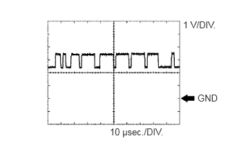
Waveform 1 (Reference) : Using an oscilloscope
| Terminal Name | CANH - GND1, GND2 |
| Tester Range | 1 V/DIV., 10 μsec./DIV. |
| Condition | Ignition switch ON |
- HINT:
-
The waveform varies depending on the CAN communication signal.
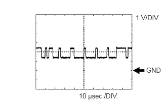
Waveform 2 (Reference) : Using an oscilloscope
| Terminal Name | CANL - GND1, GND2 |
| Tester Range | 1 V/DIV., 10 μsec./DIV. |
| Condition | Ignition switch ON |
- HINT:
-
The waveform varies depending on the CAN communication signal.
CHECK OUTER MIRROR CONTROL ECU
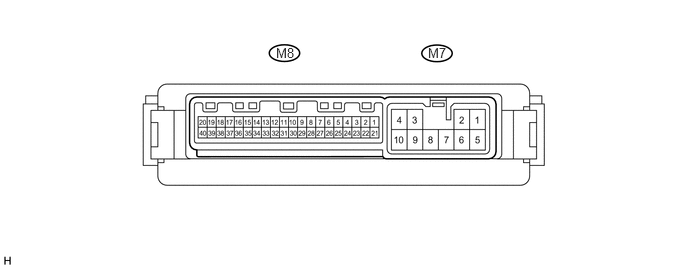
Disconnect the M7 and M8 outer mirror control ECU connectors.
Measure the voltage and resistance according to the value(s) in the table below.
| Terminal No. (Symbol) | Wiring Color | Terminal Description | Condition | Specified Condition |
|---|---|---|---|---|
| M7-3 (B) - Body ground | R - Body ground | Battery power supply | Always | 11 to 14 V |
| M7-4 (ACC) - Body ground | Y - Body ground | ACC power supply | Ignition switch
off → ACC |
Below 1 V → 11 to 14 V |
| M7-9 (GND) - Body ground | W-B - Body ground | Body ground | Always | Below 1 Ω |
If the result is not as specified, there may be a malfunction on the wire harness side.
Reconnect the M7 and M8 outer mirror control ECU connectors.
Measure the voltage according to the value(s) in the table below.
| Terminal No. (Symbol) | Wiring Color | Terminal Description | Condition | Specified Condition |
|---|---|---|---|---|
| M8-1 (CAN) - M7-9 (GND) | LG - W-B | CAN communication signal | Ignition switch ON | Pulse generation
(see waveform 1) |
| M8-17 (LP) - Body ground | V - Body ground | Puddle light LH operation signal | Puddle light LH turn on | 11 to 14 V |
| M8-21 (CGND) - M7-9 (GND) | W - W-B | CAN communication signal | Ignition switch ON | Pulse generation
(see waveform 2) |
| M8-37 (LP) - Body ground | SB - Body ground | Puddle light RH operation signal | Puddle light RH turn on | 11 to 14 V |
If the result is not as specified, the ECU may have a malfunction.
Waveform 1 (Reference) : Using an oscilloscope
| Terminal Name | CAN - GND |
| Tester Range | 1 V/DIV., 10 μsec./DIV. |
| Condition | Ignition switch ON |
- HINT:
-
The waveform varies depending on the CAN communication signal.
Waveform 2 (Reference) : Using an oscilloscope
| Terminal Name | CGND - GND |
| Tester Range | 1 V/DIV., 10 μsec./DIV. |
| Condition | Ignition switch ON |
- HINT:
-
The waveform varies depending on the CAN communication signal.