Home › Vehicle Exterior › LIGHTING (EXT) › LIGHTING SYSTEM
RM27L0U _59 Vehicle Exterior _049352 LIGHTING (EXT) _0235988 LIGHTING SYSTEM C

LIGHTING (EXT)  LIGHTING SYSTEM  B1244  Light Sensor Circuit Malfunction  


DESCRIPTION

This DTC is output when a failure of the automatic light control sensor circuit is detected.

DTC No. DTC Detection Condition Trouble Area
B1244 When either condition below is met:
·

Malfunction of light sensor

·

Open or short of light sensor circuit


·

Automatic light control sensor

·

Harness or connector

·

Main body ECU


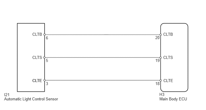
WIRING DIAGRAM

E132905E07
5.545,3.189 6.582,3.345 1.038,0.156 10 H3 5.545,3.344 6.582,3.499 1.038,0.156 10 Main Body ECU 1.124,2.711 1.590,2.857 0.466,0.147 10 CLTE 1.124,1.91 1.590,2.056 0.466,0.147 10 CLTS 1.124,1.109 1.590,1.256 0.466,0.147 10 CLTB 1.124,2.711 1.590,2.857 0.466,0.147 10 CLTE 5.684,2.711 6.150,2.857 0.466,0.147 10 CLTE 5.678,1.91 6.144,2.056 0.466,0.147 10 CLTS 5.678,1.109 6.144,1.256 0.466,0.147 10 CLTB 5.402,1.216 5.590,1.393 0.188,0.177 10 20 5.402,2.008 5.590,2.185 0.188,0.177 10 19 5.402,2.817 5.590,2.994 0.188,0.177 10 18 0.144,3.194 2.124,3.355 1.980,0.161 10 I21 0.144,3.339 2.124,3.499 1.980,0.161 10 Automatic Light Control Sensor 1.596,1.23 2.062,1.377 0.466,0.147 10 6 1.596,2.015 2.062,2.162 0.466,0.147 10 5 1.596,2.814 2.062,2.960 0.466,0.147 10 3

PROCEDURE

1.INSPECT FOR DTC

b.

Recheck for DTC (See page Vehicle Exterior>LIGHTING (EXT)>LIGHTING SYSTEM>DTC CHECK / CLEAR).

OK:

DTC B1244 is not output.


OK

NG

2.READ VALUE USING TECHSTREAM (AUTOMATIC LIGHT CONTROL SENSOR)
a.

Operate the Techstream according to the display and select Data List.

Main Body
Tester Display Measurement Item/Range Normal Condition Diagnostic Note
Illumination Rate Illumination rate / min.: 0, max.: 99.99 Actual illumination rate is displayed -

OK:

Output illumination is as shown in table above.


OK

REPLACE MAIN BODY ECU

NG

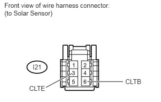
3.INSPECT AUTOMATIC LIGHT CONTROL SENSOR (SYSTEM VOLTAGE)
a.
U153922E02
1.865,1.75 2.625,1.75 true 1.542,1.573 0.979,1.875 true 0.094,0.031 2.438,0.719 2.344,0.688 10 false Front view of wire harness connector: (to Solar Sensor) 0.625,1.813 1.01,1.99 0.385,0.177 10 false CLTE 0.698,1.354 1.01,1.531 0.313,0.177 10 false I21 2.677,1.667 3.073,1.844 0.396,0.177 10 false CLTB

Disconnect the I21 automatic light control sensor connector.


b.

Measure the voltage according to the value(s) in the table below.

Standard Voltage:
Tester Connection Switch Condition Specified Condition
I21-6 (CLTB) - I21-3 (CLTE) Ignition switch ON 11 to 14 V
Ignition switch off Below 1 V


c.

Reconnect the automatic light control sensor connector.


OK

REPLACE AUTOMATIC LIGHT CONTROL SENSOR

NG

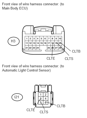
4.CHECK HARNESS AND CONNECTOR (MAIN BODY ECU - AUTOMATIC LIGHT CONTROL SENSOR)
a.
U153951E01
0.082,0.072 2.580,0.384 2.498,0.311 10 Front view of wire harness connector: (to Main Body ECU) 0.082,2.533 2.696,2.871 2.613,0.338 10 Front view of wire harness connector: (to Automatic Light Control Sensor) 1.838,2.225 2.337,2.435 0.499,0.210 10 CLTE 1.044,4.274 1.552,4.440 0.508,0.166 10 CLTE 2.557,2.243 3.056,2.452 0.499,0.210 10 CLTS 1.566,4.351 1.955,4.501 0.389,0.150 10 CLTS 2.84,1.95 3.264,2.105 0.424,0.155 10 CLTB 0.435,1.543 0.649,1.684 0.214,0.141 10 H3 0.566,3.761 0.864,3.915 0.298,0.155 10 I21 2.241,4.114 2.629,4.324 0.388,0.210 10 CLTB 2.089,1.702 2.053,2.225 false 2.219,4.172 1.808,4.031 false 1.611,3.895 1.359,4.288 false 1.634,4.072 1.761,4.343 false 2.235,1.68 2.728,2.201 false 2.792,2.023 2.376,1.677 false

Disconnect the H3 main body ECU connector.


b.

Disconnect the I21 automatic light control sensor connector.


c.

Measure the resistance according to the value(s) in the table below.

Standard Resistance:
Tester Connection Condition Specified Condition
H3-20 (CLTB) - I21-6 (CLTB) Always Below 1 Ω
H3-19 (CLTS) - I21-5 (CLTS) Always Below 1 Ω
H3-18 (CLTE) - I21-3 (CLTE) Always Below 1 Ω
H3-20 (CLTB) - Body ground Always 10 kΩ or higher
H3-19 (CLTS) - Body ground Always 10 kΩ or higher
H3-18 (CLTE) - Body ground Always 10 kΩ or higher


d.

Reconnect the automatic light control sensor connector.


e.

Reconnect the main body ECU connector.


OK

REPLACE MAIN BODY ECU

NG

REPAIR OR REPLACE HARNESS OR CONNECTOR