Home › Vehicle Exterior › LIGHTING (EXT) › LIGHTING SYSTEM
RM27L0U _59 Vehicle Exterior _049352 LIGHTING (EXT) _0235988 LIGHTING SYSTEM J

LIGHTING (EXT)  LIGHTING SYSTEM  DRL Relay Circuit  


DESCRIPTION

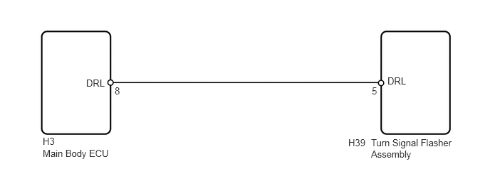
The daytime running light relay is built into the turn signal flasher assembly .

When the daytime running light relay receives the ignition switch ON signal from the main body ECU, the turn signal flasher assembly illuminates the turn signal lights. When the daytime running light relay receives the headlight dimmer switch signal, the turn signal flasher assembly turns off the turn signal lights.

WIRING DIAGRAM
E146735E04
0.625,2.167 1.719,2.563 1.094,0.396 10 false Main Body ECU 0.625,1.99 0.927,2.167 0.302,0.177 10 false H3 5.427,2.01 6.708,2.698 1.281,0.688 10 false Turn Signal Flasher Assembly 5.094,2.01 5.396,2.188 0.302,0.177 10 false H39 1.26,1.135 1.583,1.333 0.323,0.198 10 false DRL 5.667,1.104 5.99,1.302 0.323,0.198 10 false DRL 1.677,1.25 1.813,1.406 0.135,0.156 10 false 8 5.438,1.25 5.573,1.406 0.135,0.156 10 false 5

PROCEDURE

1.INSPECT MAIN BODY ECU
a.
U154069E01
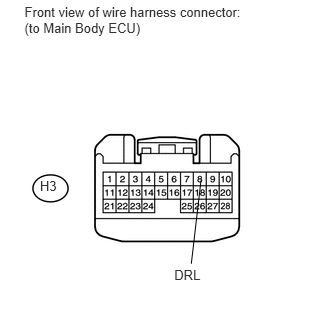
0.255,0.041 2.606,0.408 2.351,0.367 10 Front view of wire harness connector: (to Main Body ECU) 0.416,1.852 0.634,2.018 0.218,0.166 10 H3 1.815,2.781 2.148,2.951 0.333,0.170 10 DRL 2.093,1.878 1.992,2.747 false

Disconnect the H3 main body ECU connector.


b.

Measure the voltage according to the value(s) in the table below.

Standard Voltage:
Tester Connection Switch Condition Specified Condition
H3-8 (DRL) - Body ground Ignition switch ON 11 to 14 V
Ignition switch off Below 1 V


OK

PROCEED TO NEXT CIRCUIT INSPECTION SHOWN IN PROBLEM SYMPTOMS TABLE

NG

2.CHECK HARNESS AND CONNECTOR (TURN SIGNAL FLASHER ASSEMBLY - MAIN BODY ECU)
a.
U154003E02
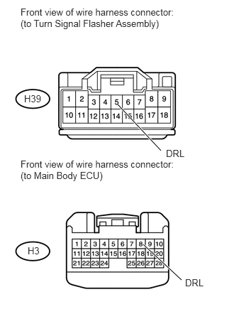
1.729,1.531 2.365,2.208 true 2.104,3.583 2.667,4.104 true 0.302,0.094 2.729,0.833 2.427,0.74 10 false Front view of wire harness connector: (to Turn Signal Flasher Assembly) 0.302,2.323 2.646,2.969 2.344,0.646 10 false Front view of wire harness connector: (to Main Body ECU) 0.354,1.365 0.667,1.531 0.313,0.167 10 false H39 0.406,3.594 0.604,3.76 0.198,0.167 10 false H3 2.438,2.167 2.75,2.344 0.313,0.177 10 false DRL 2.719,4.063 3.031,4.24 0.313,0.177 10 false DRL

Disconnect the H39 turn signal flasher assembly connector.


b.

Disconnect the H3 main body ECU connector.


c.

Measure the resistance according to the value(s) in the table below.

Standard Resistance:
Tester Connection Condition Specified Condition
H39-5 (DRL) - H3-8 (DRL) Always Below 1 Ω
H39-5 (DRL) - Body ground Always 10 kΩ or higher


d.

Reconnect the main body ECU connector.


e.

Reconnect the turn signal flasher assembly connector.


OK

REPLACE TURN SIGNAL FLASHER ASSEMBLY

NG

REPAIR OR REPLACE HARNESS OR CONNECTOR