Home › Vehicle Exterior › LIGHTING (EXT) › LIGHTING SYSTEM
RM27L0U _59 Vehicle Exterior _049352 LIGHTING (EXT) _0235988 LIGHTING SYSTEM J

LIGHTING (EXT)  LIGHTING SYSTEM  Headlight (HI-BEAM) Circuit  


DESCRIPTION

The main body ECU receives light control switch and dimmer switch information signals from the headlight dimmer switch, and illuminates the headlight high beam.

WIRING DIAGRAM
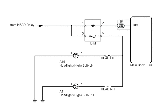
E163640E03
0.451,1.009 1.618,1.177 1.167,0.168 10 from HEAD Relay 3.994,1.833 4.281,1.994 0.287,0.161 10 DIM 3.633,0.927 3.738,1.094 0.105,0.168 10 1 3.631,1.4 3.727,1.546 0.096,0.146 10 3 4.518,0.925 4.621,1.085 0.103,0.160 10 2 4.52,1.383 4.637,1.526 0.117,0.143 10 5 5.258,1.038 5.495,1.180 0.237,0.143 10 DB 5.279,0.865 5.465,1.020 0.187,0.155 10 16 5.763,2.79 6.785,2.964 1.022,0.174 10 Main Body ECU 4.463,2.489 5.095,2.650 0.633,0.161 10 HEAD LH 4.463,3.863 5.127,4.024 0.664,0.161 10 HEAD RH 2.634,2.649 2.903,2.816 0.268,0.168 10 A10 2.634,2.812 4.216,2.986 1.581,0.174 10 Headlight (High) Bulb LH 2.634,3.954 2.903,4.122 0.268,0.168 10 A11 2.634,4.117 4.216,4.291 1.581,0.174 10 Headlight (High) Bulb RH 3.112,3.633 3.217,3.801 0.105,0.168 10 1 3.549,3.633 3.652,3.793 0.103,0.160 10 2 3.112,2.258 3.217,2.425 0.105,0.168 10 1 3.549,2.258 3.652,2.418 0.103,0.160 10 2 5.875,1.025 6.156,1.209 0.281,0.184 10 DIM

PROCEDURE

1.PERFORM ACTIVE TEST USING TECHSTREAM (HEADLIGHT (HIGH))
a.

Connect the Techstream to the DLC3.


b.

Turn the ignition switch to ON.


c.

Turn the Techstream on.


d.

Enter the following menus: Body Electrical / Main Body / Active Test / Head Light Hi


e.

Check that the headlight (high) turns on/off.

Main Body
Tester Display Test Part Control Range Diagnostic Note
Head Light Hi Headlight (High) ON or OFF -

OK:

Headlight (High) turns on/off.


OK

PROCEED TO NEXT CIRCUIT INSPECTION SHOWN IN PROBLEM SYMPTOMS TABLE

NG

2.INSPECT FUSE (HEAD LH, HEAD RH)
a.
E161570E09
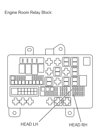
2.458,3 1.313,4.125 true 2.479,3.208 2.729,4.135 false 0.156,0.333 1.99,0.563 1.833,0.229 10 false Engine Room Relay Block: 0.698,4.125 1.323,4.281 0.625,0.156 10 false HEAD LH 2.333,4.146 2.979,4.302 0.646,0.156 10 false HEAD RH

Remove the HEAD LH and HEAD RH fuse from the engine room relay block.


b.

Measure the resistance according to the value(s) in the table below.

Standard Resistance:
Tester Connection Condition Specified Condition
HEAD LH fuse Always Below 1 Ω
HEAD RH fuse Always Below 1 Ω


c.

Reinstall the HEAD LH and HEAD RH fuses.


OK

3.INSPECT HEADLIGHT (HIGH) BULB

NG

REPLACE FUSE

3.INSPECT HEADLIGHT (HIGH) BULB
a.

Temporarily replace the headlight (high) bulb with a new or normally functioning one (See page Vehicle Exterior>LIGHTING (EXT)>HEADLIGHT ASSEMBLY>DISASSEMBLY).


b.

Check that the headlight (high) come on.

OK:

Headlight (high) come on.


OK

END

NG

4.CHECK HARNESS AND CONNECTOR (HEADLIGHT (HIGH) BULB - HEADLIGHT DIMMER RELAY)
U153964E01
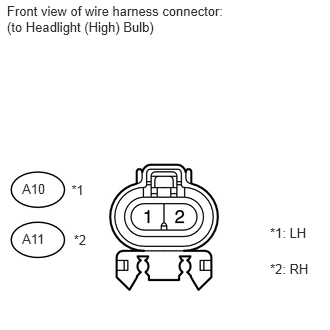
0.072,0.035 2.444,0.400 2.372,0.365 10 Front view of wire harness connector: (to Headlight (High) Bulb) 0.23,1.882 0.516,2.048 0.286,0.166 10 A10 0.23,2.407 0.516,2.574 0.286,0.166 10 A11 0.744,1.897 0.914,2.051 0.171,0.154 10 *1 0.768,2.416 0.919,2.578 0.151,0.162 10 *2 2.813,2.341 3.263,2.515 0.450,0.174 10 *1: LH 2.813,2.719 3.256,2.865 0.443,0.147 10 *2: RH

a.

for LH:

i.

Disconnect the A10 headlight (high) LH connector.


ii.

Measure the voltage according to the value(s) in the table below.

Standard Voltage:
Tester Connection Switch Condition Specified Condition
A10-2 - Body ground Light control switch HEAD, dimmer switch High 11 to 14 V
Light control switch HEAD, dimmer switch except High Below 1 V


iii.

Reconnect the headlight (high) LH connector.


b.

for RH:

i.

Disconnect the A11 headlight (high) RH connector.


ii.

Measure the voltage according to the value(s) in the table below.

Standard Voltage:
Tester Connection Switch Condition Specified Condition
A11-2 - Body ground Light control switch HEAD, dimmer switch High 11 to 14 V
Light control switch HEAD, dimmer switch except High Below 1 V


iii.

Reconnect the headlight (high) RH connector.


OK

REPAIR OR REPLACE HARNESS OR CONNECTOR (HEADLIGHT HIGH BULB - BODY GROUND)

NG

5.INSPECT HEADLIGHT DIMMER RELAY (DIM)
A111813E28
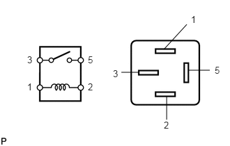
2.448,0.74 2.792,0.365 false 2.813,1.052 3.135,1.052 false 2.063,1.083 1.813,1.083 false 2.49,1.438 2.49,1.792 false 2.854,0.208 3.01,0.375 0.156,0.167 10 false 1 0.406,1.219 0.563,1.385 0.156,0.167 10 false 1 1.688,1.021 1.844,1.188 0.156,0.167 10 false 3 0.406,0.813 0.563,0.979 0.156,0.167 10 false 3 2.448,1.792 2.604,1.958 0.156,0.167 10 false 2 1.313,1.219 1.469,1.385 0.156,0.167 10 false 2 3.208,0.969 3.365,1.135 0.156,0.167 10 false 5 1.313,0.813 1.469,0.979 0.156,0.167 10 false 5

a.

Remove the DIM relay from the engine room relay block.

b.

Measure the resistance according to the value(s) in the table below.

Standard Resistance:
Tester Connection Condition Specified Condition
3 - 5 When battery voltage is not applied to terminals 1 and 2 10 kΩ or higher
When battery voltage is applied to terminals 1 and 2 Below 1 Ω


c.

Reinstall the DIM relay.


OK

6.CHECK HARNESS AND CONNECTOR (DIM RELAY - HEAD RELAY)

NG

REPLACE DIM RELAY

6.CHECK HARNESS AND CONNECTOR (DIM RELAY - HEAD RELAY)
U154009E01
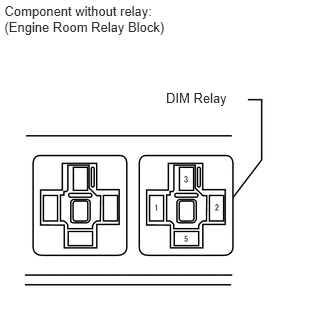
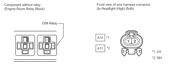
0.046,0.034 1.868,0.385 1.823,0.350 10 Component without relay: (Engine Room Relay Block) 1.729,0.94 2.416,1.090 0.687,0.150 10 DIM Relay

a.

Remove the DIM relay from the engine room relay block.


b.

Measure the voltage according to the value(s) in the table below.

Standard Voltage:
Tester Connection Switch Condition Specified Condition
DIM relay terminal 1 - Body ground Light control switch HEAD, dimmer switch Low 11 to 14 V
DIM relay terminal 3 - Body ground Light control switch HEAD, dimmer switch Low 11 to 14 V


c.

Reinstall the DIM relay.


OK

7.CHECK HARNESS AND CONNECTOR (DIM RELAY - HEADLIGHT (HIGH) BULB)

NG

REPAIR OR REPLACE HARNESS OR CONNECTOR

7.CHECK HARNESS AND CONNECTOR (DIM RELAY - HEADLIGHT (HIGH) BULB)
a.

Remove the DIM relay from the engine room relay block.

E344948E01
3.969,1.427 4.344,1.719 0.375,0.292 3.969,1.875 4.344,2.167 0.375,0.292 2.344,1.906 2.625,1.542 2.625,1.542 2.625,0.979 false 2.417,0.979 2.625,0.979 false 0.177,0.115 1.969,0.552 1.792,0.438 10 false Component without relay: (Engine Room Relay Block) 1.75,0.885 2.438,1.115 0.688,0.229 10 false DIM Relay 4.01,0.104 6.354,0.552 2.344,0.448 10 false Front view of wire harness connector: (to Headlight (High) Bulb) 4.031,1.49 4.323,1.698 0.292,0.208 10 false A10 4.031,1.938 4.323,2.146 0.292,0.208 10 false A11 4.406,1.49 4.615,1.688 0.208,0.198 10 false *1 4.427,1.927 4.635,2.125 0.208,0.198 10 false *2 6.292,2.073 6.823,2.25 0.531,0.177 10 false *1: LH 6.302,2.333 6.833,2.51 0.531,0.177 10 false *2: RH


b.

for LH:

i.

Disconnect the A10 headlight (high) LH connector.


ii.

Measure the resistance according to the value(s) in the table below.

Standard Resistance:
Tester Connection Condition Specified Condition
DIM relay terminal 5 - A10-2 Always Below 1 Ω
DIM relay terminal 5 - Body ground Always 10 kΩ or higher


iii.

Reconnect the headlight (high) LH connector.


c.

for RH:

i.

Disconnect the A11 headlight (high) RH connector.


ii.

Measure the resistance according to the value(s) in the table below.

Standard Resistance:
Tester Connection Condition Specified Condition
DIM relay terminal 5 - A11-2 Always Below 1 Ω
DIM relay terminal 5 - Body ground Always 10 kΩ or higher


iii.

Reconnect the headlight (high) RH connector.


d.

Reinstall the DIM relay.


OK

8.CHECK HARNESS AND CONNECTOR (DIM RELAY - MAIN BODY ECU)

NG

REPAIR OR REPLACE HARNESS OR CONNECTOR

8.CHECK HARNESS AND CONNECTOR (DIM RELAY - MAIN BODY ECU)
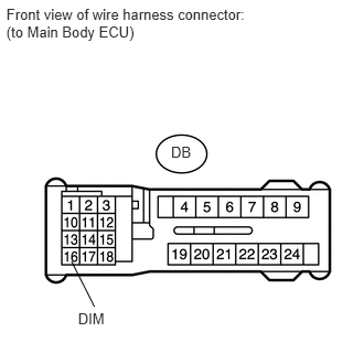
U154007E01
0.06,0.049 2.445,0.399 2.385,0.350 10 Front view of wire harness connector: (to Main Body ECU) 1.615,1.355 1.841,1.511 0.225,0.156 10 DB 0.737,2.931 1.049,3.080 0.312,0.149 10 DIM 0.892,2.897 0.675,2.467 false

a.

Disconnect the DB main body ECU connector.


b.

Measure the voltage according to the value(s) in the table below.

Standard Voltage:
Tester Connection Switch Condition Specified Condition
DB-16 - Body ground Light control switch HEAD 11 to 14 V


c.

Reconnect the main body ECU connector.


OK

REPLACE MAIN BODY ECU

NG

REPAIR OR REPLACE HARNESS OR CONNECTOR