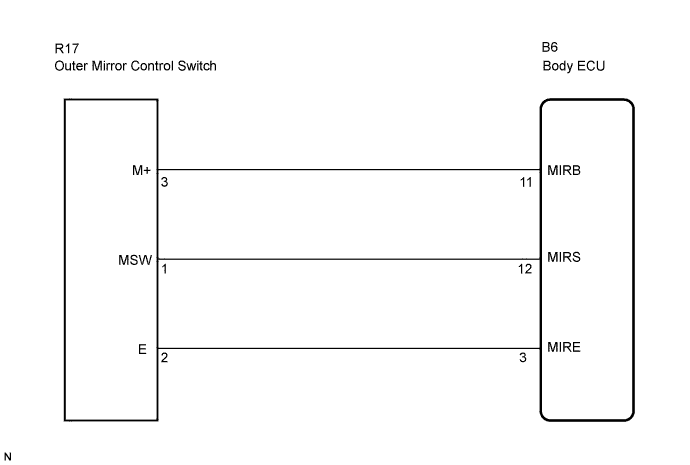
POWER MIRROR CONTROL SYSTEM (w/ Memory) > Mirror Switch Circuit |
| 1.INSPECT OUTER MIRROR SWITCH |
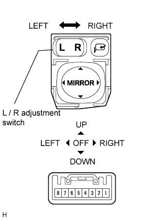 |
Remove the outer mirror control switch.
Measure the resistance according to the value(s) in the table below when the switch is operated.
| Tester Connection | Switch Position | Specified Condition |
| 2 - 3 | OFF | 10 kΩ or higher |
| UP + L or R (*1) | 80 to 120 Ω | |
| DOWN + L or R (*1) | 450 to 490 Ω | |
| LEFT + L or R (*1) | 780 to 820 Ω | |
| RIGHT + L or R (*1) | 230 to 270 Ω | |
| 1 - 2 | L | 90 to 110Ω |
| R | 10 Ω or less |
|
| ||||
| OK | |
 |
| 2.CHECK WIRE HARNESS (OUTER MIRROR SWITCH - MAIN BODY ECU RH) |
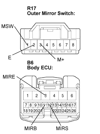 |
Disconnect the B6 ECU connector.
Measure the resistance according to the value(s) in the table below.
| Tester Connection (Symbols) | Condition | Specified Condition |
| R17-3 (M+) - B6-11 (MIRB) | Always | Below 1 Ω |
| R17-1 (MSW) - B6-12 (MIRS) | Always | Below 1 Ω |
| R17-2 (E) - B6-3 (MIRE) | Always | Below 1 Ω |
| R17-3 (M+) - Body ground | Always | 10 kΩ or higher |
| R17-1 (MSW) - Body ground | Always | 10 kΩ or higher |
| R17-2 (E) - Body ground | Always | 10 kΩ or higher |
|
| ||||
| OK | ||
 | ||
| ||
