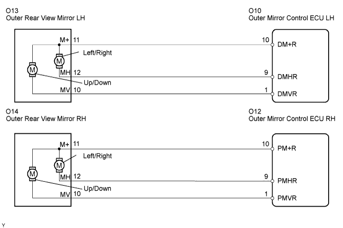
POWER MIRROR CONTROL SYSTEM (w/ Memory) > Mirror Motor Circuit |
| 1.PERFORM ACTIVE TEST USING TECHSTREAM |
Connect Techstream to the DLC3.
Ignition switch on.
Select the ACTIVE TEST, use Techstream to issue a control command, and then check that the outer rear view mirrors.
| Tester Display | Test Part | Control Range | Diagnostic Note |
| Mirror Up/Down | Mirror vertical operation: | Up/Down | - |
| Mirror Right/Left | Mirror horizontal operation: | Right/Left | - |
|
| ||||
| NG | |
 |
| 2.INSPECT OUTER REAR VIEW MIRROR |
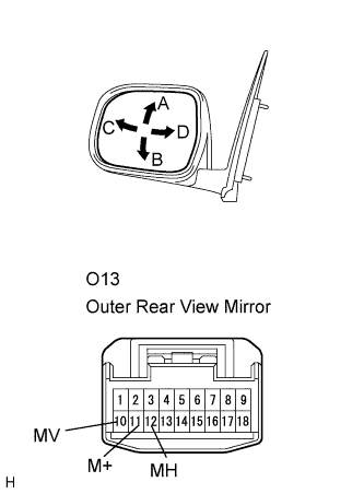 |
Outer rear view mirror LH:
Disconnect the O13 connector.
Apply battery voltage and check operation of the mirror face.
| Measurement Condition (Symbols) | Mirror Operation |
| Battery positive (+) → O13-10 (MV) Battery negative (-) → O13-11 (M+) | Turns upward (A) |
| Battery positive (+) → O13-11 (M+) Battery negative (-) → O13-10 (MV) | Turns downward (B) |
| Battery positive (+) → O13-12 (MH) Battery negative (-) → O13-11 (M+) | Turns left (C) |
| Battery positive (+) → O13-11 (M+) Battery negative (-) → O13-12 (MH) | Turns right (D) |
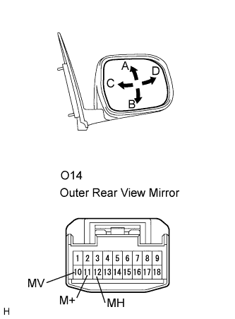 |
Outer rear view mirror RH:
Disconnect the O14 connector.
Apply battery voltage and check operation of the mirror face.
| Measurement Condition (Symbols) | Mirror Operation |
| Battery positive (+) → O14-10 (MV) Battery negative (-) → O14-11 (M+) | Turns upward (A) |
| Battery positive (+) → O14-11 (M+) Battery negative (-) → O14-10 (MV) | Turns downward (B) |
| Battery positive (+) → O14-12 (MH) Battery negative (-) → O14-11 (M+) | Turns left (C) |
| Battery positive (+) → O14-11 (M+) Battery negative (-) → O14-12 (MH) | Turns right (D) |
|
| ||||
| OK | |
|
| 3.CHECK HARNESS AND CONNECTOR (OUTER REAR VIEW MIRROR - OUTER MIRROR CONTROL ECU) |
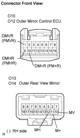 |
Disconnect the O10 or O12 ECU connector.
Measure the resistance according to the value(s) in the table below.
| Terminals No. (Symbols) | Condition | Specified Condition |
| O10-10 (DM+R) - O13-11 (M+) (*1) | Always | Below 1 Ω |
| O12-10 (PM+R) - O14-11 (M+) (*2) | Always | Below 1 Ω |
| O10-9 (DMHR) - O13-12 (MH) (*1) | Always | Below 1 Ω |
| O12-9 (PMHR) - O14-12 (MH) (*2) | Always | Below 1 Ω |
| O10-1 (DMVR) - O13-10 (MV) (*1) | Always | Below 1 Ω |
| O12-1 (PMVR) - O14-10 (MV) (*2) | Always | Below 1 Ω |
| O10-10 (DM+R) - Body ground (*1) | Always | 10 kΩ or higher |
| O12-10 (PM+R) - Body ground (*2) | Always | 10 kΩ or higher |
| O10-9 (DMHR) - Body ground (*1) | Always | 10 kΩ or higher |
| O12-9 (PMHR) - Body ground (*2) | Always | 10 kΩ or higher |
| O10-1 (DMVR) - Body ground (*1) | Always | 10 kΩ or higher |
| O12-1 (PMVR) - Body ground (*2) | Always | 10 kΩ or higher |
|
| ||||
| OK | ||
 | ||
| ||
