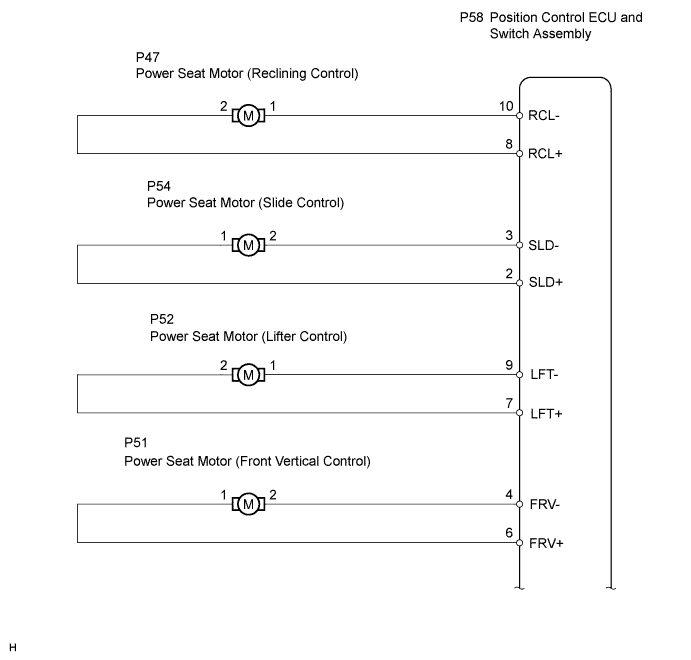
FRONT POWER SEAT CONTROL SYSTEM > Power Seat Motor Circuit |
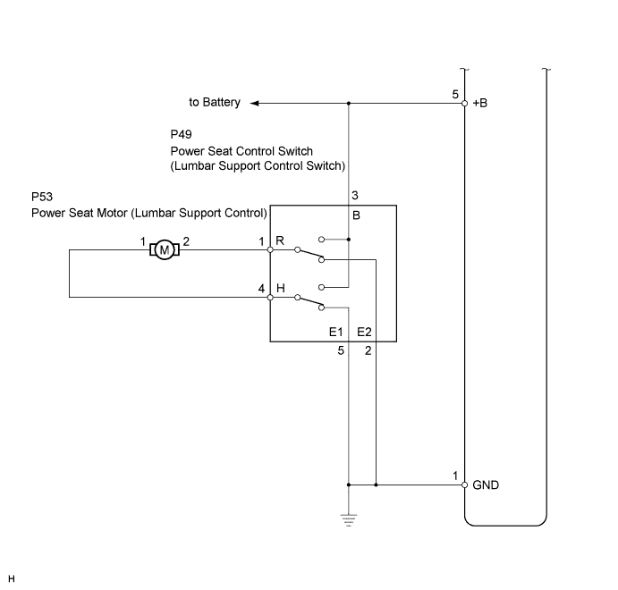
| 1.CHECK FRONT POWER SEAT OPERATION |
Check that each function of the power seat operates normally by using the front power seat switches.
| Result | Proceed to |
| All front power seat switch operations are malfunctioning except lumbar front power seat switch operation | A |
| Only lumbar front seat switch operation is malfunctioning | B |
|
| ||||
| A | |
 |
| 2.READ VALUE USING TECHSTREAM (FRONT POWER SEAT SWITCH) |
Check the Data List for proper functioning of the front power seat switch.
| Tester Display | Measurement Item/Range | Normal Condition | Diagnostic Note |
| Reclining Rear | Reclining switch signal (Rearward) / ON or OFF | ON: Reclining switch (Rearward) is ON OFF: Reclining switch (Rearward) is OFF | - |
| Reclining Front | Reclining switch signal (Forward) / ON or OFF | ON: Reclining switch (Forward) is ON OFF: Reclining switch (Forward) is OFF | - |
| Front Vertical Down | Front vertical switch signal (Downward) / ON or OFF | ON: Front vertical switch (Downward) is ON OFF: Front vertical switch (Downward) is OFF | - |
| Front Vertical UP | Front vertical switch signal (Upward) / ON or OFF | ON: Front vertical switch (Upward) is ON OFF: Front vertical switch (Upward) is OFF | - |
| Lifter Switch Down | Lifter switch signal (Downward) / ON or OFF | ON: Lifter switch (Downward) is ON OFF: Lifter switch (Downward) is OFF | - |
| Lifter Switch UP | Lifter switch signal (Upward) / ON or OFF | ON: Lifter switch (Upward) is ON OFF: Lifter switch (Upward) is OFF | - |
| Slide Rear | Sliding switch signal (Rearward) / ON or OFF | ON: Sliding switch (Rearward) is ON OFF: Sliding switch (Rearward) is OFF | - |
| Slide Front | Sliding switch signal (Forward) / ON or OFF | ON: Sliding switch (Forward) is ON OFF: Sliding switch (Forward) is OFF | - |
|
| ||||
| OK | |
|
| 3.PERFORM ACTIVE TEST USING TECHSTREAM (POWER SEAT MOTOR) |
Select the Active Test, use Techstream to generate a control command, and then check that the power seat motors operate.
| Tester Display | Test Part | Control Range | Diagnostic Note |
| Seat Reclining | Seat reclining operation | FRONT / REAR | - |
| Front Vertical Operation | Seat front vertical operation | UP / DOWN | - |
| Lifter Operation | Seat lifter operation | UP / DOWN | - |
| Seat Slide Operation | Seat sliding operation | FRONT / REAR | - |
|
| ||||
| OK | ||
 | ||
| ||
| 4.INSPECT FRONT SEAT ADJUSTER SUB-ASSEMBLY (POWER SEAT MOTOR) |
Inspect the power seat motor (Click here).
|
| ||||
| OK | |
|
| 5.CHECK HARNESS AND CONNECTOR (POSITION CONTROL ECU AND SWITCH ASSEMBLY - POWER SEAT MOTOR) |
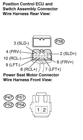 |
Disconnect the position control ECU and switch assembly connector and power seat motor connectors.
Measure the resistance according to the value(s) in the table below.
| Tester Connection | Condition | Specified Condition |
| P58-2 (SLD+) - P54-1 | Always | Below 1 Ω |
| P58-3 (SLD-) - P54-2 | Always | Below 1 Ω |
| P58-4 (FRV-) - P51-2 | Always | Below 1 Ω |
| P58-6 (FRV+) - P51-1 | Always | Below 1 Ω |
| P58-7 (LFT+) - P52-2 | Always | Below 1 Ω |
| P58-9 (LFT-) - P52-1 | Always | Below 1 Ω |
| P58-8 (RCL+) - P47-2 | Always | Below 1 Ω |
| P58-10 (RCL-) - P47-1 | Always | Below 1 Ω |
| P58-2 (SLD+) - Body ground | Always | 10 kΩ or higher |
| P58-3 (SLD-) - Body ground | Always | 10 kΩ or higher |
| P58-4 (FRV-) - Body ground | Always | 10 kΩ or higher |
| P58-6 (FRV+) - Body ground | Always | 10 kΩ or higher |
| P58-7 (LFT+) - Body ground | Always | 10 kΩ or higher |
| P58-9 (LFT-) - Body ground | Always | 10 kΩ or higher |
| P58-8 (RCL+) - Body ground | Always | 10 kΩ or higher |
| P58-10 (RCL-) - Body ground | Always | 10 kΩ or higher |
|
| ||||
| OK | ||
| ||
| ||
| 6.CHECK WIRE HARNESS (POWER SEAT CONTROL SWITCH - BATTERY AND BODY GROUND) |
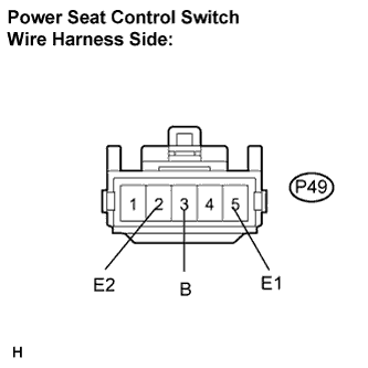 |
Disconnect the P49 switch connector.
Measure the voltage and resistance of the wire harness side connectors.
| Tester Connection | Specified Condition |
| P49-3 (B) - Body ground | 10 to 14 V |
| Tester connection | Specified condition |
| P49-2 (E2) - Body ground | Below 1 Ω |
| P49-5 (E1) - Body ground | Below 1 Ω |
|
| ||||
| OK | |
|
| 7.INSPECT POWER SEAT CONTROL SWITCH (LUMBER SUPPORT CONTROL) |
Inspect the power seat control switch (Click here).
|
| ||||
| OK | |
|
| 8.INSPECT FRONT SEAT ADJUSTER SUB-ASSEMBLY (POWER SEAT MOTOR) |
Inspect the power seat motor (Click here).
|
| ||||
| OK | ||
| ||
| ||

