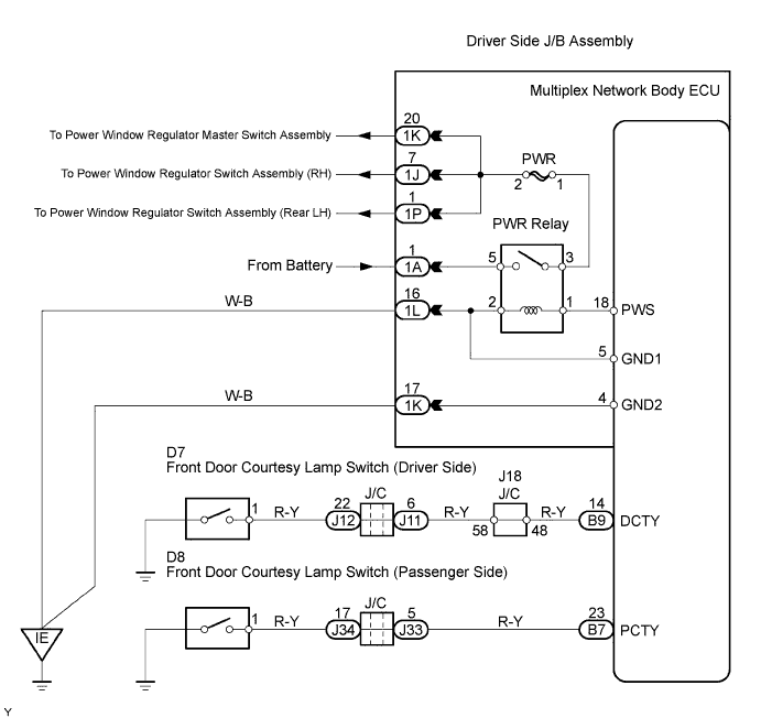
POWER WINDOW CONTROL SYSTEM (w/ Jam Protection Function) > Power Window can be Operated After Ignition Switch is Turned OFF Even if Operative Conditions are not Met |
| 1.CHECK CHECK OPERATION FUNCTION AFTER IGNITION SWITCH IS TURNED OFF |
If the power window operates even after either front door is opened within 45 seconds after the ignition switch is turned OFF, proceed to A.
If the power window operates even after 45 seconds have passed after the ignition switch is turned OFF, proceed to B.
|
| ||||
| A | |
 |
| 2.READ VALUE USING TECHSTREAM |
Using Techstream, check that the data list for proper functioning of the front door courtesy switches.
| Tester Display | Measurement Item/Range | Normal Condition | Diagnostic Note |
| D Door Courtesy SW | Driver side door courtesy switch signal/ON or OFF | ON: Driver side door is open OFF: Driver side door is closed | - |
| P Door Courtesy SW | Passenger side door courtesy switch signal/ ON or OFF | ON: Passenger side door is open OFF: Passenger side door is closed | - |
|
| ||||
| NG | |
|
| 3.INSPECT DOOR COURTESY SWITCH ASSEMBLY |
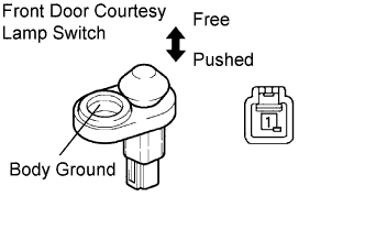 |
Remove the courtesy lamp switch.
Check the switch resistance.
| Terminal No. | Condition | Specified Condition |
| 1 - Body ground | Switch pushed | 10 kΩ or higher |
| Switch free | Below 1 Ω |
|
| ||||
| OK | |
|
| 4.CHECK WIRE HARNESS (FRONT DOOR COURTESY SWITCH - MULTIPLEX NETWORK BODY ECU) |
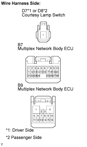 |
Disconnect the D7 or D8 lamp switch connector.
Disconnect the B7 or B9 ECU connector.
Check the resistance between the wire harness side connectors.
| Terminal No. | Specified Condition |
| D7-1 - B9-14 (DCTY) | Below 1 Ω |
| D8-1 - B7-23 (PCTY) | Below 1 Ω |
|
| ||||
| OK | ||
 | ||
| ||
