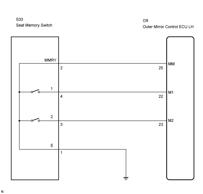
POWER MIRROR CONTROL SYSTEM (w/ Memory) > Memory Switch Circuit |
| 1.READ VALUE USING TECHSTREAM |
Connect Techstream to the DLC3.
Ignition switch on.
Check the DATA LIST for proper function of the seat memory switch.
| Tester Display | Test Part | Normal condition | Diagnostic Note |
| Driver Mirror Memory No1 | Driver side mirror position memorized in seat memory switch M 1/NOT MEM or MEM | MEM: Memorized NOT MEM: Not memorized | - |
| Driver Mirror Memory No2 | Driver side mirror position memorized in seat memory switch M 2/NOT MEM or MEM | MEM: Memorized NOT MEM: Not memorized | - |
| Passenger Mirror Mem No1 | Passenger side mirror position memorized in seat memory switch M 1/NOT MEM or MEN | MEM: Memorized NOT MEM: Not memorized | - |
| Passenger Mirror Mem No2 | Passenger side mirror position memorized in seat memory switch M 2/NOT MEM or MEN | MEM: Memorized NOT MEM: Not memorized | - |
|
| ||||
| NG | |
 |
| 2.INSPECT SEAT MEMORY SWITCH |
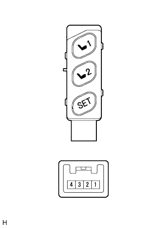 |
Remove the seat memory switch.
Measure the resistance according to the value(s) in the table below when the switch is operated.
| Tester Connection | Switch Condition | Specified Condition |
| 1 - 2 | "SET" switch ON | Below 1 Ω |
| 1 - 2 | "SET" switch OFF | 10 kΩ or higher |
| 1 - 4 | "1" switch ON | Below 1 Ω |
| 1 - 4 | "1" switch OFF | 10 kΩ or higher |
| 1 - 3 | "2" switch ON | Below 1 Ω |
| 1 - 3 | "2" switch OFF | 10 kΩ or higher |
|
| ||||
| OK | |
|
| 3.CHECK HARNESS AND CONNECTOR (SEAT MEMORY SWITCH - OUTER MIRROR CONTROL ECU) |
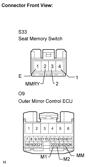 |
Disconnect the S33 switch connector.
Disconnect the O9 ECU connector.
Measure the resistance according to the value(s) in the table below.
| Tester Connection (Symbols) | Condition | Specified Condition |
| S33-2 (MMRY) - O9-25 (MM) | Always | Below 1 Ω |
| S33-4 (1) - O9-22 (M1) | Always | Below 1 Ω |
| S33-3 (2) - O9-23 (M2) | Always | Below 1 Ω |
| S33-1 (E) - Body ground | Always | Below 1 Ω |
| S33-2 (MMRY) - Body ground | Always | 10 kΩ or higher |
| S33-4 (1) - Body ground | Always | 10 kΩ or higher |
| S33-3 (2) - Body ground | Always | 10 kΩ or higher |
|
| ||||
| OK | ||
 | ||
| ||
