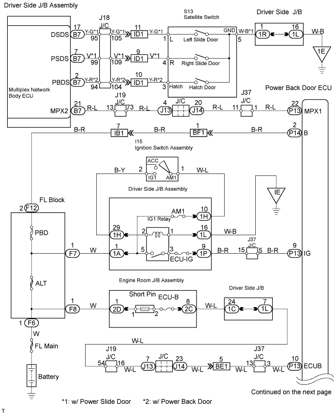
POWER BACK DOOR SYSTEM > Power Back Door does not Operate |
| 1.BASIC INSPECTION |
Conditions necessary for the power back door to open:
Power back door main switch is in the ON position (switch free: orange paint on the top of the switch appears).
Back door is between the fully closed position and approximately around the half-open position.
Shift lever is in the P position when the ignition switch is ON (When the ignition switch is OFF, the power back door operates in any position of the shift lever.)
Conditions necessary for the power back door to close:
Power back door main switch is in the ON position (switch free: orange paint on the top of the switch appears).
Back door is between approximately around the half-open position and the fully open position.
Back door touch sensor is not damaged and deformed.
| OK | |
 |
| 2.INSPECT FUSE (ECU-B, ECU IG, AM1) |
Inspect the ECU-B, ECU IG and AM1 fuses.
|
| ||||
| OK | |
|
| 3.CHECK DTC |
Check for DTC B2222. DTC B2222 indicates a pulse sensor malfunction.
Without code outputs, proceed to A.
With code outputs, proceed to B.
|
| ||||
| A | |
|
| 4.INSPECT COMMUNICATION FUNCTION OF LARGE-SCALE MULTIPLEX COMMUNICATION SYSTEM (BEAN) |
Use the Techstream to check for normal function of the multiplex communication system.
(ECU unconnected, communication line malfunctioning) Without DTC B1214, B1215 or B1287 outputs, proceed to A.
(ECU unconnected, communication line malfunctioning) With DTC B1214, B1215 or B1287 outputs, proceed to B.
|
| ||||
| A | |
|
| 5.READ VALUE USING TECHSTREAM |
Using the Techstream, check the DATA LIST for proper functioning of the power back door main switch.
| Item | Measurement Item / Display (Range) | Normal Condition | Diagnostic Note |
| PBD Main SW | Power back door main switch signal / ON or OFF | ON: Orange paint on top of the switch appears OFF: Orange paint on top of the switch does not appear | - |
|
| ||||
| NG | |
|
| 6.INSPECT POWER BACK DOOR MAIN SWITCH |
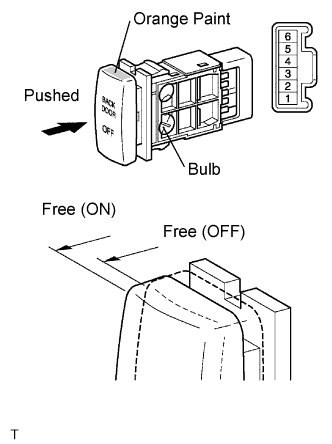 |
Inspect the resistance of the main switch.
| Terminal No. | Condition | Specified Condition |
| 4 - 5 | Free (ON) | Below 1 Ω |
| Pushed (OFF) | 10 kΩ or higher |
|
| ||||
| OK | |
|
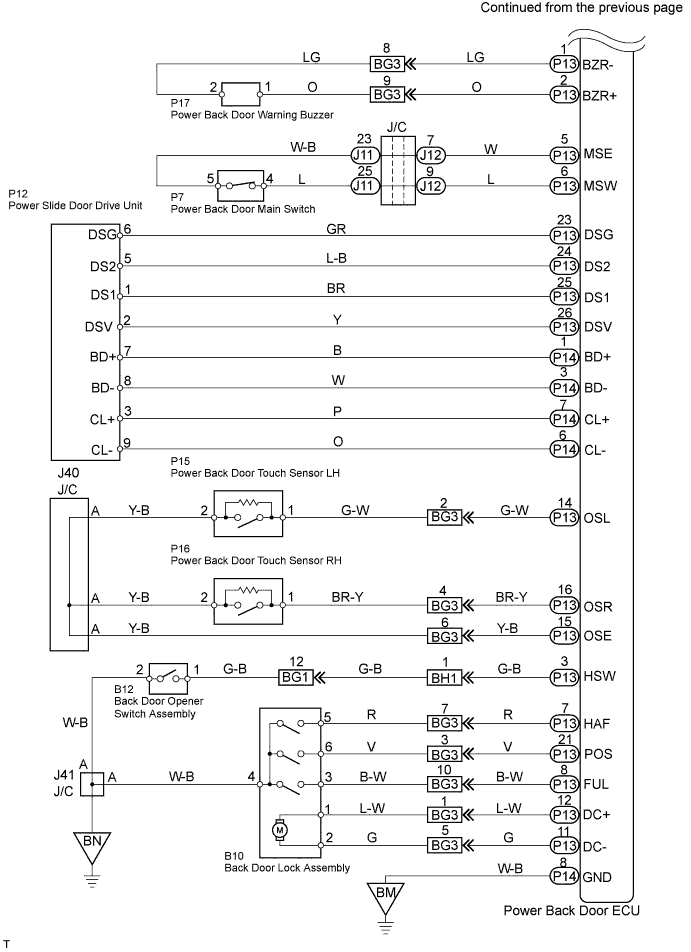
| 7.CHECK WIRE HARNESS (POWER BACK DOOR MAIN SWITCH - POWER BACK DOOR ECU) |
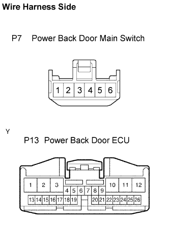 |
Disconnect the P7 main switch and P13 ECU connectors.
Check the resistance between the wire harness side connectors.
| Terminal No. | Specified Condition |
| P7-4 - P13-6 (MSW) | Below 1 Ω |
| P7-5 - P13-5 (MSE) |
|
| ||||
| OK | ||
 | ||
| ||
| 8.CHECK SWITCH OPERATION |
If the power back door does not respond to using the satellite switch, proceed to A.
If the power back door does not respond to using the back door opener switch outside, proceed to B.
|
| ||||
| A | |
|
| 9.INSPECT SATELLITE SWITCH |
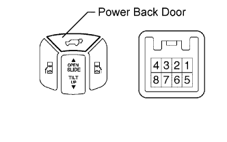 |
Inspect the resistance of the back door switch.
| Terminal No. | Condition | Specified Condition |
| 3 - 5 | Free | 10 kΩ or higher |
| Pushed | Below 1 Ω |
|
| ||||
| OK | |
|
| 10.CHECK WIRE HARNESS (SATELLITE SWITCH - DRIVER SIDE J/B, BODY GROUND) |
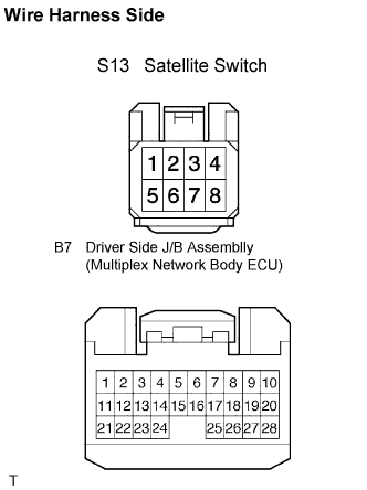 |
Disconnect the S13 switch and the B7 ECU connectors.
Check the resistance between the wire harness side connectors.
| Terminal No. | Specified Condition |
| S13-3 (HATCH) - B7-2 (PBDS) | Below 1 Ω |
Check the resistance between the S13 switch connector and body ground.
| Terminal No. | Specified Condition |
| S13-5 (GND) - Body ground | Below 1 Ω |
|
| ||||
| NG | ||
| ||
| ||
| 11.READ VALUE USING TECHSTREAM |
Using the Techstream, check the DATA LIST for proper functioning of the back door opener switch (Outside handle switch).
| Item | Measurement Item / Display (Range) | Normal Condition | Diagnostic Note |
| Back Door Handle SW | Back door opener switch signal / ON or OFF | ON: Back door opener switch is pushed OFF: Back door opener switch is not pushed | - |
|
| ||||
| NG | |
|
| 12.INSPECT BACK DOOR OPENER SWITCH ASSEMBLY (OUTSIDE HANDLE SWITCH) |
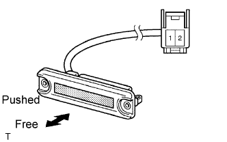 |
Inspect the resistance of the switch.
| Terminal No. | Condition | Specified Condition |
| 1 - 2 | Free | 10 kΩ or higher |
| Pushed | Below 1 Ω |
|
| ||||
| OK | |
|
| 13.CHECK WIRE HARNESS (BACK DOOR OPENER SWITCH - POWER BACK DOOR ECU AND GROUND) |
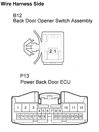 |
Disconnect the B12 switch and P13 ECU connectors.
Check the resistance between the wire harness side connectors.
| Terminal No. | Specified Condition |
| B12-1 - P13-3 (HSW) | Below 1 Ω |
Check the resistance between the B12 switch connector and body ground.
| Terminal No. | Specified Condition |
| B12-2 - Body ground | Below 1 Ω |
|
| ||||
| OK | ||
| ||
| ||
| 14.READ VALUE USING TECHSTREAM |
Using the Techstream, check the DATA LIST for proper functioning of the power back door touch sensor LH.
| Item | Measurement Item / Display (Range) | Normal Condition | Diagnostic Note |
| PBD Touch Sensor (Left) | Power back door touch sensor LH signal / OFF, ON or OPEN | OFF: Power back door touch sensor LH is free ON: Power back door touch sensor LH is pressed OPEN: Power back door touch sensor LH is opened | - |
|
| ||||
| NG | |
|
| 15.INSPECT POWER BACK DOOR TOUCH SENSOR LH |
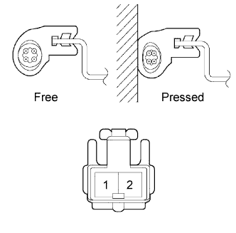 |
Check the resistance of the sensor.
| Terminal No. | Condition | Specified Condition |
| 1 - 2 | Free | Approx. 1 kΩ |
| Pressed | Less than 100 Ω |
|
| ||||
| OK | |
|
| 16.CHECK WIRE HARNESS (POWER BACK DOOR TOUCH SENSOR LH - POWER BACK DOOR ECU) |
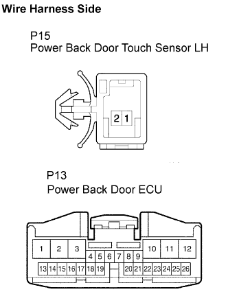 |
Disconnect the P15 sensor and P13 ECU connectors.
Check the resistance between the wire harness side connectors.
| Terminal No. | Specified Condition |
| P15-1 - P13-14 (OSL) | Below 1 Ω |
| P15-2 - P13-15 (OSE) |
|
| ||||
| OK | ||
| ||
| ||
| 17.READ VALUE USING TECHSTREAM |
Using the Techstream, check the DATA LIST for proper functioning of the power back door touch sensor RH.
| Item | Measurement Item / Display (Range) | Normal Condition | Diagnostic Note |
| PBD Touch Sensor (Right) | Power back door touch sensor RH signal / OFF, ON or OPEN | OFF: Power back door touch sensor RH is free ON: Power back door touch sensor RH is pressed OPEN: Power back door touch sensor RH is opened | - |
|
| ||||
| NG | |
|
| 18.INSPECT POWER SLIDE DOOR WARNING BUZZER RH |
|
Check the resistance of the sensor.
| Terminal No. | Condition | Specified Condition |
| 1 - 2 | Free | Approx. 1 kΩ |
| Pressed | Less than 100 Ω |
|
| ||||
| OK | |
|
| 19.CHECK WIRE HARNESS (POWER BACK DOOR TOUCH SENSOR RH - POWER BACK DOOR ECU) |
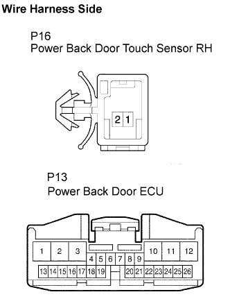 |
Disconnect the P16 sensor and P13 ECU connectors.
Check the resistance between the wire harness side connectors.
| Terminal No. | Specified Condition |
| P16-1 - P13-16 (OSR) | Below 1 Ω |
| P16-2 - P13-15 (OSE) |
|
| ||||
| OK | ||
| ||
| ||
| 20.PERFORM ACTIVE TEST USING TECHSTREAM |
Select the ACTIVE TEST and then check that the power back door drive unit operates.
| Item | Test Details | Diagnostic Note |
| PBD Motor | Power back door motor is operate OFF / FORWARD / REVERSE | Clutch is OFF while power slide door motor is operating |
| PBD Clutch | Power back door clutch is operate OFF / ON | Power slide door motor is OFF when clutch is ON |
|
| ||||
| NG | |
|
| 21.INSPECT POWER BACK DOOR DRIVE UNIT |
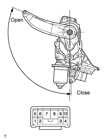 |
Remove the unit.
Connect the battery positive (+) lead to terminal 3 and battery negative (-) terminal lead to terminal 9.
Apply battery voltage to the terminals and check the motor operation.
| Measurement Condition | Specified Condition |
| Battery positive (+) → Terminal 8 Battery negative (-) → Terminal 7 | Open |
| Battery positive (+) → Terminal 7 Battery negative (-) → Terminal 8 | Close |
Check the resistance of the clutch terminals.
| Terminal No. | Specified Condition |
| 3 - 9 | 4.0 Ω |
Reinstall the unit with the connector connected.
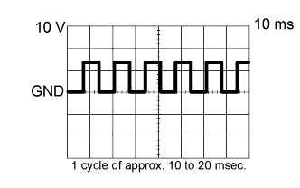 |
Check the pulse of the pulse sensor.
Using an oscilloscope, check the pulse generated when the door is manually opened and closed.
| Terminal | Tool setting | Vehicle condition |
| 1 - 6, 5 - 6 | 10 V/DIV., 10 ms/DIV. | Door moving |
|
| ||||
| OK | |
|
| 22.CHECK WIRE HARNESS (POWER BACK DOOR DRIVE UNIT - POWER BACK DOOR ECU) |
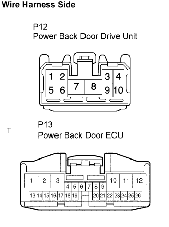 |
Disconnect the P12 unit and P13 ECU connectors.
Check the resistance between the wire harness side connectors.
| Terminal No. | Specified Condition |
| P12-6 (DSG) - P13-23 (DSG) | Below 1 Ω |
| P12-5 (DS2) - P13-24 (DS2) | |
| P12-1 (DS1) - P13-25 (DS1) | |
| P12-2 (DSV) - P13-26 (DSV) |
|
| ||||
| OK | ||
| ||
| ||
| 23.READ VALUE USING TECHSTREAM |
Using the Techstream, check the DATA LIST for proper functioning of the switches listed below.
| Item | Measurement Item / Display (Range) | Normal Condition | Diagnostic Note |
| Half Latch SW | Back door lock half latch switch signal / ON or OFF | ON: Back door is not completely closed OFF: Back door is closed | - |
| Full Latch SW | Back door lock full latch switch signal / ON or OFF | ON: Back door is opened OFF: Back door is closed | - |
|
| ||||
| NG | |
|
| 24.INSPECT BACK DOOR LOCK ASSEMBLY |
|
| ||||
| OK | |
|
| 25.CHECK WIRE HARNESS (BACK DOOR LOCK ASSEMBLY - POWER BACK DOOR ECU) |
|
| ||||
| OK | |
|
| 26.REPLACE POWER BACK DOOR ECU |
Check the power back door for normal OPEN / CLOSE operation.
|
| ||||
| OK | ||
| ||
| ||

