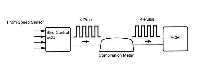
DTC P0500 Vehicle Speed Sensor "A" |
| DTC No. | DTC Detection Condition | Trouble Area |
| P0500 | The ECM detects the following conditions simultaneously for 2 seconds (1 trip detection logic):
|
|
| Related DTCs | P0500: Vehicle speed sensor "A" pulse input error |
| Required Sensors / Components (Main) | Vehicle Speed Sensor (VSS), Combination meter and Skid control ECU |
| Required Sensors / Components (Related) | Park/neutral Position (PNP) switch, Engine Coolant Temperature (ECT) sensor, Crankshaft Position (CKP) sensor and Mass Air Flow (MAF) meter |
| Frequency of Operation | Continuous |
| Duration | 2 seconds |
| MIL Operation | Immediate |
| Sequence of Operation | None |
| The monitor will run whenever these DTCs are not present | None |
| Time after ignition switch OFF to ON | 3 seconds or more |
| Engine | Running |
| Transmission counter gear speed | 300 rpm or more |
| Battery voltage | 8 V or more |
| Ignition switch | ON |
| Starter | OFF |
| Either of the following conditions is met | Condition 1 or 2 |
| 1. Both of the following conditions are met | Condition (a) or (b) |
| (a) ECT | 20°C (68°F) or more |
| (b) ECT sensor fail (P0115,P0117,P0118,P0125) | Not detected |
| (c) Time after PNP switch ON to OFF | 2 seconds or more |
| 2. Both of the following conditions are met | Conditions (a) and (b) |
| (a) ECT | Less than 20°C (68°F) |
| (b) ECT sensor fail (P0115,P0117,P0118,P0125) | Detected |
| (c) Time after PNP switch ON to OFF | 30 seconds or more |
| Vehicle speed sensor signal | No signal |
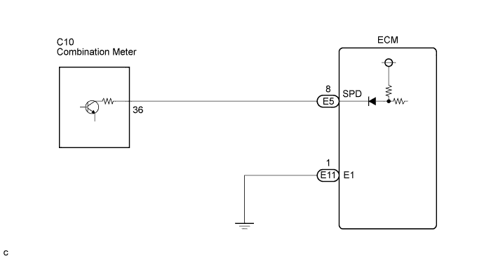
| 1.CHECK SPEEDOMETER |
Drive the vehicle and check whether the operation of the speedometer in the combination meter is normal.
|
| ||||
| OK | |
 |
| 2.READ VALUE USING TECHSTREAM (VEHICLE SPEED) |
Connect the Techstream to the DLC3.
Turn the ignition switch to the ON position.
Turn the tester on.
Select the following menu items: Powertrain / Engine and ECT / Data List / Vehicle Speed.
Drive the vehicle.
Read the value displayed on the tester.
|
| ||||
| OK | |
|
| 3.CHECK COMBINATION METER ASSEMBLY (+S VOLTAGE) |
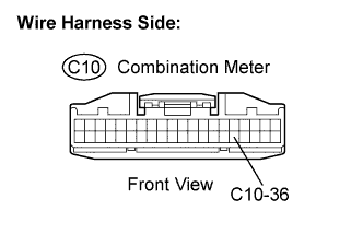 |
Disconnect the C10 combination meter connector.
Turn the ignition switch to the ON position.
Measure the voltage between the terminal of the combination meter and body ground.
| Tester Connection | Specified Condition |
| C10-36 - Body ground | 4.5 to 5.5 V |
Reconnect the combination meter connector.
|
| ||||
| OK | |
|
| 4.CHECK COMBINATION METER ASSEMBLY (SPD SIGNAL WAVEFORM) |
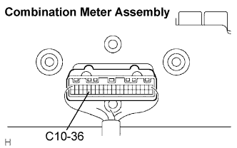 |
Shift the transmission gear selector lever to the neutral position.
Jack up the vehicle.
Turn the ignition switch to the ON position.
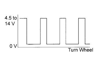 |
Measure the voltage between the terminal of the combination meter and body ground while the wheel is turned slowly.
| Tester Connection | Specified Condition |
| C10-36 - Body ground | Voltage generated intermittently |
|
| ||||
| OK | |
|
| 5.CHECK HARNESS AND CONNECTOR (COMBINATION METER ASSEMBLY - ECM) |
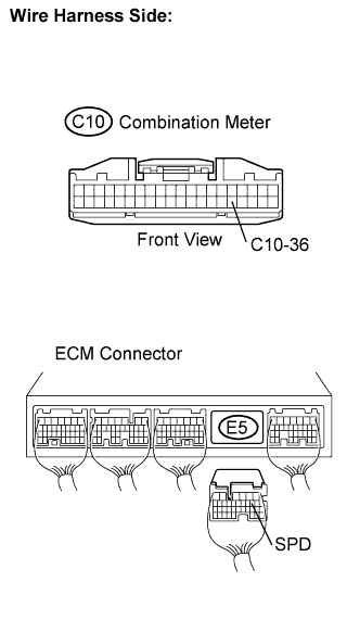 |
Disconnect the C10 combination meter connector.
Disconnect the E5 ECM connector.
Measure the resistance.
| Tester Connection | Specified Condition |
| C10-36 - SPD (E5-8) | Below 1 Ω |
| Tester Connection | Specified Condition |
| C10-36 or SPD (E5-8) - Body ground | 10 kΩ or higher |
Reconnect the combination meter connector.
Reconnect the ECM connector.
|
| ||||
| OK | ||
 | ||
| ||

