INTERIOR PANELS / TRIM FRONT CONSOLE BOX INSTALLATION
CAUTION / NOTICE / HINT
- HINT:
- ·
Use the same procedure for LHD and RHD vehicles.
·The following procedure is for LHD vehicles.
PROCEDURE

 58510H
1.INSTALL FLOOR MAT ASSEMBLY
- HINT:
- ·
Perform this procedure only when replacement of the floor mat assembly is necessary.
·Use the same procedures for the front passenger side.
Install the No. 1 mat set plates in the front floor carpet assembly and turn by 90°.
- HINT:
-
Perform this procedure only when replacement of the No. 1 mat set plate is necessary.
Install the floor mat assembly.
2.INSTALL FOOTWELL STORAGE NET
- HINT:
-
Perform this procedure only when replacement of the footwell storage net is necessary.
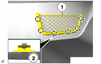
Attach the clips (2) to install the footwell storage net (1).
3.INSTALL EMERGENCY LOUDSPEAKER
- HINT:
-
Perform this procedure only when replacement of the No. 1 instrument panel under cover sub-assembly is necessary.
-
Click hereAudio / Visual / Telematics>TELEMATICS>EMERGENCY LOUDSPEAKER>INSTALLATION
81080J
4.INSTALL NO. 1 INTERIOR ILLUMINATION LIGHT ASSEMBLY (w/ Foot light)
- HINT:
-
Perform this procedure only when replacement of the instrument panel under cover sub-assembly is necessary.
- ·
for Driver Side
Click hereVehicle Interior>LIGHTING (INT)>FOOTWELL LIGHT>INSTALLATION
·for Front Passenger Side
Click hereVehicle Interior>LIGHTING (INT)>FOOTWELL LIGHT>INSTALLATION
58911G
5.INSTALL NO. 1 BOX PANEL
- HINT:
-
Perform this procedure only when replacement of the No. 1 box panel is necessary.
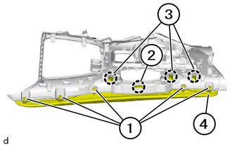
Attach the guides (3) and claw (2) to install the No. 1 box panel (4).
Tighten the T20 screws (1).
- Torque:
- 3.0 N*m (31 kgf*cm, 27 in.*lbf)
84780A
6.INSTALL REMOTE OPERATION CONTROLLER ASSEMBLY
- HINT:
-
Perform this procedure only when replacement of the upper console panel sub-assembly is necessary.
-
Click hereAudio / Visual / Telematics>NAVIGATION / MULTI INFO DISPLAY>MULTI-DISPLAY CONTROLLER>INSTALLATION
84390B
7.INSTALL ELECTRIC PARKING BRAKE SWITCH ASSEMBLY
- HINT:
-
Perform this procedure only when replacement of the upper console panel sub-assembly is necessary.
-
Click hereBrake>PARKING BRAKE>ELECTRIC PARKING BRAKE SWITCH>INSTALLATION
84720J
8.INSTALL PATTERN SELECT SWITCH ASSEMBLY
- HINT:
-
Perform this procedure only when replacement of the upper console panel sub-assembly is necessary.
-
Click hereVehicle Interior>INTERIOR PANELS / TRIM>COMBINATION SWITCH (for Console Box)>INSTALLATION
86190C
9.INSTALL NO. 1 STEREO JACK ADAPTER ASSEMBLY
- HINT:
-
Perform this procedure only when replacement of the front console box cover is necessary.
-
Click hereAudio / Visual / Telematics>AUDIO / VIDEO>STEREO JACK ADAPTER ASSEMBLY>INSTALLATION
58916
10.INSTALL BOX BOTTOM MAT (w/o Wireless Charger)
- HINT:
-
Perform this procedure only when replacement of the box bottom mat insert is necessary.
Install the box bottom mat.
861C0
11.INSTALL MOBILE WIRELESS CHARGER CRADLE ASSEMBLY (w/ Wireless Charger)
- HINT:
-
Perform this procedure only when replacement of the front console box cover is necessary.
-
Click hereVehicle Interior>POWER OUTLETS (INT)>WIRELESS CHARGER ASSEMBLY>INSTALLATION
55900
12.INSTALL AIR CONDITIONING CONTROL ASSEMBLY
- HINT:
-
Perform this procedure only when replacement of the instrument panel finish lower panel is necessary.
-
Click hereVehicle Interior>HEATING / AIR CONDITIONING>AIR CONDITIONING PANEL>INSTALLATION
58821A
13.INSTALL CONSOLE PANEL
- HINT:
-
Perform this procedure only when replacement of the console panel or console panel retainer is necessary.
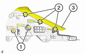
Attach the clips (2) to install the console panel (3).
Tighten the T20 screws (1).
- Torque:
- 2.3 N*m (23 kgf*cm, 20 in.*lbf)
55618A
14.INSTALL CONSOLE BOX CUP HOLDER
- HINT:
-
Perform this procedure only when replacement of the console box cup holder is necessary.
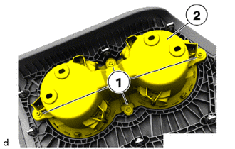
Install the console box cup holder (2).
Tighten the T20 screws (1).
- Torque:
- 2.3 N*m (23 kgf*cm, 20 in.*lbf)
58801D
15.INSTALL CONSOLE BOX ASSEMBLY
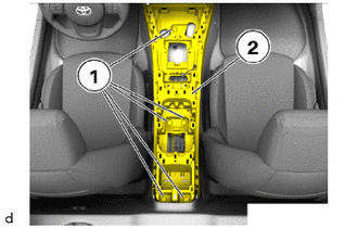
Install the console box assembly (2).
Tighten the bolts (1).
- Torque:
- 4.6 N*m (47 kgf*cm, 41 in.*lbf)
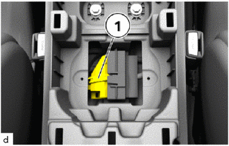
Connect the connector and lock (1).
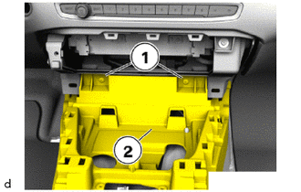
Tighten the T20 screws (1) on the console box assembly (2) on the front.
- Torque:
- 1.8 N*m (18 kgf*cm, 16 in.*lbf)
Tighten the T20 screw on the console box assembly on the right.
- Torque:
- 1.8 N*m (18 kgf*cm, 16 in.*lbf)
Tighten the T20 screw on the console box assembly on the left.
- Torque:
- 1.8 N*m (18 kgf*cm, 16 in.*lbf)
55607
16.INSTALL NO. 2 INSTRUMENT PANEL UNDER COVER SUB-ASSEMBLY
Connect associated connector.
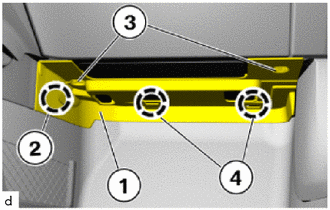
Attach the guides (4).
Attach the guide (2) to install the No. 2 instrument panel under cover sub-assembly (1).
Position locks (3) correctly and turn by 90°.
55606
17.INSTALL NO. 1 INSTRUMENT PANEL UNDER COVER SUB-ASSEMBLY
for LHD:
Connect and lock the relevant connectors.
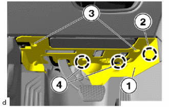
Attach the guides (4).
Attach the guide (2) to install the No. 1 instrument panel under cover sub-assembly (1).
Turn the locks (3) by 90°.
for RHD:
Connect and lock the relevant connectors.
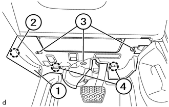
Attach the guides (4).
Attach the guide (2) to install the No. 1 instrument panel under cover sub-assembly (1).
Turn the locks (3) by 90°.
33550
18.INSTALL TRANSMISSION FLOOR SHIFT ASSEMBLY
58804A
19.INSTALL UPPER CONSOLE PANEL SUB-ASSEMBLY
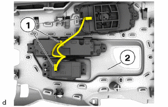
Connect connectors (1) and lock.
Position the upper console panel sub-assembly (2).
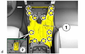
Attach the clips (2) to install the upper console panel sub-assembly (1).
58818A
20.INSTALL FRONT CONSOLE BOX COVER
w/o Wireless Charger:
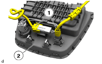
Connect and lock the connectors (1) to the front console box cover (2).
w/ Wireless Charger:
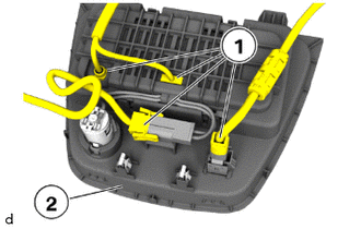
Connect and lock the connectors (1) to the front console box cover (2).
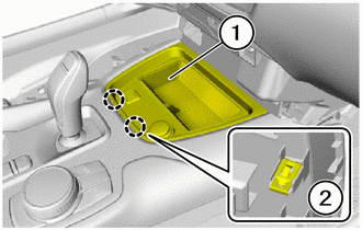
Attach the clips (2) to install the front console box cover (1).
55432B
21.INSTALL INSTRUMENT PANEL FINISH LOWER PANEL
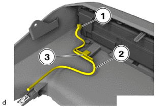
Connect connectors (1) and lock.
Attach the clip (3) to install the wiring harness (2).
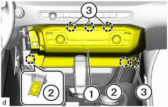
Attach the guides (3) and clips (2) to install the instrument panel finish lower panel (1).
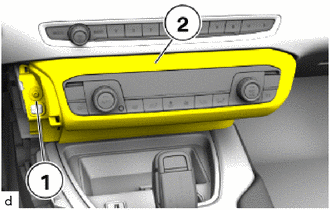
Tighten the T20 screw (1) on the instrument panel finish lower panel (2).
- Torque:
- 1.8 N*m (18 kgf*cm, 16 in.*lbf)
Open the glove compartment door assembly.
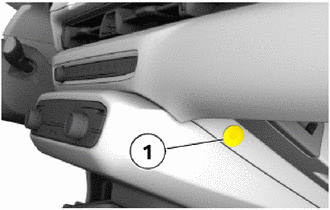
Tighten the T20 screw.
- Torque:
- 1.8 N*m (18 kgf*cm, 16 in.*lbf)
Replace rubber plug (1).
Install the rubber plug (1).
22.INSTALL CONSOLE PANEL AND CONSOLE PANEL RETAINER
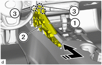

|
Install in this Direction |
Attach the guides (3) to install the console panel (1) and console panel retainer (2) as shown in the illustration.
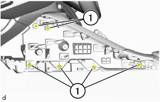
Tighten the T20 screws (1).
- Torque:
- 2.3 N*m (23 kgf*cm, 20 in.*lbf)
58822
23.INSTALL CONSOLE SIDE PANEL
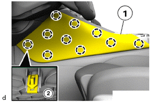
Attach the clips (2) to install the console side panel (1).
58822A
24.INSTALL CONSOLE UPPER REAR PANEL
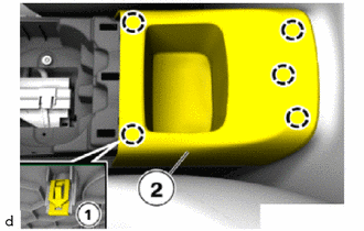
Attach the clips (1) to install the console upper rear panel (2).
Install the No. 2 console box silencer pad.
58920C
25.INSTALL FRONT CONSOLE ARMREST ASSEMBLY
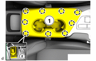
Attach the clips (2) to install the front console armrest assembly (1).
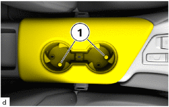
Tighten the T20 screws (1).
- Torque:
- 2.3 N*m (23 kgf*cm, 20 in.*lbf)
No. 1 console box silencer pad.
26.CONNECT CABLE TO NEGATIVE BATTERY TERMINAL
for B48:
for B58: