SUPPLEMENTAL RESTRAINT SYSTEMS CENTER AIRBAG SENSOR ASSEMBLY INSTALLATION
PROCEDURE

 89170A
1.INSTALL AIRBAG ECU ASSEMBLY
Check that the START-STOP button (engine switch) off.
- HINT:
-
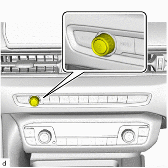
-
Pressing and holding the AUDIO button changes the power source mode to IG OFF.
Check that the cable is disconnected from the negative (-) battery terminal.
- CAUTION:
- ·
Wait at least 60 seconds after disconnecting the cable from the negative (-) battery terminal to disable the SRS system.
·If the airbag deploys for any reason, it may cause a serious accident.
Install the airbag ECU assembly (2).
Replace the nuts (1).
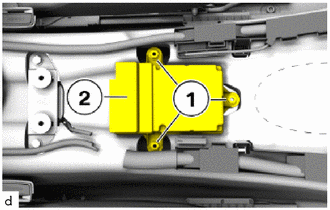
Tighten the nuts (1).
- Torque:
- 8.0 N*m (82 kgf*cm, 71 in.*lbf)
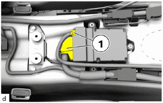
Connect the connectors (1) and lock.
58801D
2.INSTALL CONSOLE BOX ASSEMBLY
3. ENCODE/PROGRAM CONTROL UNIT(S)
- NOTICE:
- ·
Use the most recent software version to prevent faults during programming/encoding.
·The battery voltage must not drop below 13.0 V during programming.
·Use only recommended chargers for a low-voltage vehicle electrical system.
·Do not exceed the maximum charging voltage of 14.8 V when charging the battery.
·When there is communication abnormality in the middle of work, control unit might be damaged.
·It may be necessary to perform the Action Plan several times.
Connect the battery charger to the vehicle.
Connect the diagnosis system with the vehicle.
Determine the action plan.
Service plan / Programming plan / Action plan / Calculate action plan
Accept and fully process the measures plan.
Service plan / Programming plan / Action plan / Perform action plan
Wait until programming/encoding has been completed.
- NOTICE:
-
When there is communication abnormality in the middle of work, control unit might be damaged.
Carry out vehicle test.
Vehicle management / Troubleshooting / Fault memory / Calculate test plan
Delete the fault memory.
Vehicle management / Troubleshooting / Fault memory / Delete fault memory
Disconnect the diagnosis system from the vehicle.
Disconnect the battery charger from the vehicle.
89170A
4.ADJUST AIRBAG ECU ASSEMBLY
Connect the diagnosis system to the vehicle and enter the following menus:
Service functions / Chassis / Traction control system / Adjustment of the driving dynamics sensors